Home > Digital CMOS Design > Pass Transistor Logic > 2 1 MUX using transmission gate
2 : 1 MUX using transmission gate
2 : 1 MUX using transmission gate :
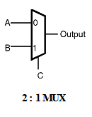
A 2:1 multiplexer is shown in Figure below. This gate selects either input A or B on the basis of the value of the control signal 'C'.When control signal C is logic low the output is equal to the input A and when control signal C is logic high the output is equal to the input B.
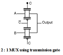
A 2 : 1 multiplexer can be implemented using transmission gates. Figure below shows the connection diagram of the 2 : 1 multiplexer using transmission gates. The 2 : 1 MUX selects either A or B depending upon the control signal C. This is equivalent to implementing the Boolean function,
F = (A C + B ––C)
When the control signal C is high then the upper transmission gate is ON and it passes A through it so that output = A.

When the control signal C is low then the upper transmission gate turns OFF and it will not allow A to pass through it, at the same time the lower transmission gate is 'ON' and it allows B to pass through it so the output = B.
