Home > VHDL > Introduction > Structure of VHDL Program
Structure of VHDL Program :
Every VHDL program consists of at least one entity/architecture pair. In a large design, you will typically write many entity/architecture pairs and connect them together to form a complete circuit. An entity declaration describes the circuit as it appears from the “outside” - from the perspective of its input and output interfaces. The second part of a minimal VHDL design description is the architecture declaration.
ENTITY is the list with specifications of all input and output pins of the circuit. Its syntax is shown below :
  ENTITY name IS
  PORT (
  port_name : signal_mode signal_type;
  port_name : signal_mode signal_type;
  ...
  );
  END name;
The mode of the signal used may be IN, OUT, INOUT or BUFFER. IN and OUT are unidirectional pins, while INOUT is bidirectional. BUFFER, is used when the output signal is used internally in the design. The type of the signal may be BIT, STD_LOGIC, INTEGER, etc. The name of the entity should be not use the VHDL reserved words.
Example :
Let us consider the NAND gate, Its ENTITY may be declared as :
  ENTITY nand_Two IS
  PORT (a, b : IN BIT;
  x : OUT BIT
  );
  END nand_Two;
ARCHITECTURE :
The ARCHITECTURE is the description of how the circuit of design works. Its syntax is as follows,
  ARCHITECTURE architecture_name OF entity_name IS
  [declarations]
  BEGIN
  (code)
  END architecture_name;
As shown in above syntax, architecture has two parts, 1) A declarative part where signals and constants are declared and 2) The code part. The name of architecture is any name except VHDL reserved words.
Example : Let us consider the NAND gate architecture,
  ARCHITECTURE arch OF nand_Two IS
  BEGIN
  x <= a NAND b;
  END arch;
The architecture indicates that the circuit is performing NAND operation between the two input signals a and b and assigning the result to the output pin (x).
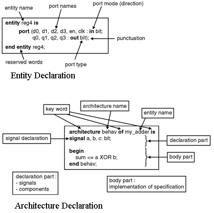
Figure below shows the detailed description of entity and architecture declarations in the VHDL program.
Modeling styles in VHDL coding are used to specify the architectural body of the design. The modeling styles can be selected depending upon the complexity of the digital design.
The modeling styles are categorized as :
- Data flow modeling (Concurrent code)
- Behavioral modeling (Sequential code)
- Structural modeling
- Mixed modeling.