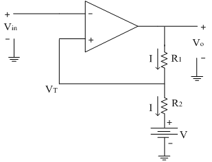
In previous section we have seen that the triggering points VLT and VUT are having same magnitudes. If we want to the upper and lower threshold values to be different then an additional battery of potential 'V' is added as shown below.
To find the triggering points:
Applying KVL at the output side, we get
Vo=IR1+IR2+V
∴I=(Vo-V)/((R1+R2 ) )
From circuit diagram, the threshold (triggering) point can be calculated as
VT=IR2+V
Substituting the equation of 'I' in above equation, we get
VT=[(Vo-V)/(R1+R2 )] R2+V
VT=R2/(R1+R2 ) Vo-R2/(R1+R2 ) V+V
VT=R2/(R1+R2 ) Vo+V[1-R2/(R1+R2 )]
VT=R2/(R1+R2 ) Vo+R1/(R1+R2 ) V
When Vout=+Vsat , VT=+ve
When Vout=-Vsat , VT= -ve
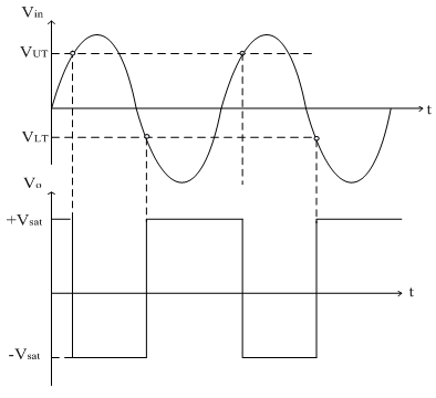
The input and output waveforms are shown below.
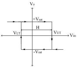
The transfer characteristics are shown below,