As we saw the circuit of the inductors operated on the direct current and we know that when DC battery voltage is used by connecting it in parallel with the inductor, the current flowing through the inductor is not instantly and is evaluated by the inductors self-induced or back emf value. Further, the current in the inductor rises continuously unless and until the current reaches to the maximum steady state value. In addition we know that, the maximum current passing through the inductive coil is limited by the resistive part of the coil and measured in Ohms and determined using the ratio of voltage to current.
When alternating current or the sinusoidal voltage is applied across the inductor then the current flows differently as compare to DC battery voltage application. The effect of a sinusoidal voltage produces the phase change between voltage and the current. Further, in alternating current circuits the resistance to the flow of electrical current not only depends upon the inductance but also on the operating frequency. This kind of opposition to the flow of current the circuit is called as impedance. However, the resistance is the main component in DC circuits and the resistive component involved in AC circuit is called as the reactance.
Since this ac resistance is provided by the inductor of the circuit, this kind of reactance is called as the inductive reactance. Similar to resistance, the inductive reactance is measured in Ohm's and denoted by the symbol X. The inductive reactance is also denoted by the symbol XL, and is opposes the change in the current. As we know that, capacitive circuit AC circuit, the current IC leads to the voltage by 90o. Similarly, in the inductive AC circuit, the current IL lags the applied voltage by 90o.
Inductor AC Circuit
Figure below shows the inductive circuit AC circuit consisting of inductor connected to the AC supply. When the AC supply voltage increases and decreases with the frequency change, the self-induced emf in the inductor also changes in the coil accordingly with the chanes in the AC supply voltage. As we know that, self-induced emf is directly proportional to the rate of change of current flowing in the inductor. As the supply voltage changes in positive cycle to negative cycle the current also changes.

The rate of change of the voltage happens when the sine wave crosses the maximum or minimum voltage level. According to these voltage levels the maximum and minimum currents are flowing in the inductor. Figure bellow shows the variations in the voltage and current levels of the inductive AC circuit.
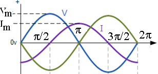
From above voltage and current waveforms we can see that, inductive AC circuit the current lags the voltage by 90o. In the similar fashion the voltage leads the current by 90o. We can also say that VL = 0o and IL = -90o Thus, if voltage waveform is sine wave then the current waveform negative cosine wave. Hence, the equations of voltage and current waveforms are given by,
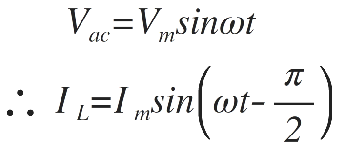
As shown in the above equation the current always lags the voltage by 90o in the inductive AC circuits. Therefore if we know the value of VL, then IL lag by 90o and if we know the value of IL then VL lead by 90o. This voltage to current ratio in the inductive AC circuit gives the inductive reactance XL of the inductor. Therefore, the inductive reactance is given by,

The above equation can also be written in the form of frequency of the supply voltage. Hence, the inductive reactance in the form of frequency is given by,

Where Æ’ is the Frequency,
L is the Inductance of the Coil and
2πƒ = ω.
Thus, inductive reactance increases if the supply frequency increases.Further, inductive reactance increases if the inductance of the coil connected in the AC circuit increases. Hence, if the operating frequency increases upto infinity the inductive reactance of the circuit also increases to infinity and acts as the open circuit. On the other hand if the operating frequency is zero i.e. DC signal then the inductive reactance is zero and acts as the short circuit. Figure below shows the variation of inductive reactance as a function of operating frequency of the supply voltage in the inductive AC circuit.
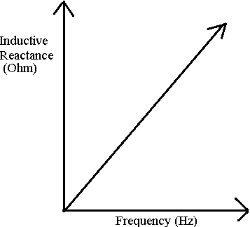
Thus, from above figure we can conclude that, inductive reactance is directly prpotional to the operating frequency of the AC supply voltage.