An induction motor has 2 main parts; the Stator and Rotor. The Stator is the stationary part and the rotor is the rotating part. The Rotor sits inside the Stator. There will be a small gap between rotor and stator, known as air-gap. The value of the radial air-gap may vary from 0.5 to 2 mm. An induction motor therefore does not require mechanical commutation, separate-excitation or self-excitation for all or part of the energy transferred from stator to rotor, as in universal, DC and large synchronous motors. An induction motor’s rotor can be either wound type or squirrel-cage type.
• Three-phase squirrel-cage induction motors are widely used in industrial drives because they are rugged, reliable and economical. Single-phase induction motors are used extensively for smaller loads, such as household appliances like fans.
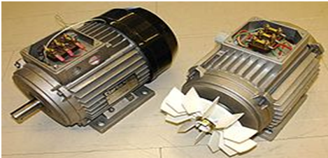
• Although traditionally used in fixed-speed service, induction motors are increasingly being used with variable-frequency drives (VFDs) in variable-speed service. Figure below shows the Induction motor.
Principles of operation
• In both induction and synchronous motors, the AC power supplied to the motor’s stator creates a magnetic field that rotates in time with the AC oscillations. Whereas a synchronous motor’s rotor turns at the same rate as the stator field, an induction motor’s rotor rotates at a slower speed than the stator field. The induction motor stator’s magnetic field is therefore changing or rotating relative to the rotor.
• This induces an opposing current in the induction motor’s rotor, in effect the motor’s secondary winding, when the latter is short-circuited or closed through an external impedance. The rotating magnetic flux induces currents in the windings of the rotor, in a manner similar to currents induced in a transformer’s secondary winding(s).
• The currents in the rotor windings in turn create magnetic fields in the rotor that react against the stator field. Due to Lenz’s Law, the direction of the magnetic field created will be such as to oppose the change in current through the rotor windings.
• The cause of induced current in the rotor windings is the rotating stator magnetic field, so to oppose the change in rotor-winding currents the rotor will start to rotate in the direction of the rotating stator magnetic field.
• The rotor accelerates until the magnitude of induced rotor current and torque balances the applied load. Since rotation at synchronous speed would result in no induced rotor current, an induction motor always operates slower than synchronous speed.
• For rotor currents to be induced, the speed of the physical rotor must be lower than that of the stator’s rotating magnetic field ( ); otherwise the magnetic field would not be moving relative to the rotor conductors and no currents would be induced.
Synchronous speed
An AC motor’s synchronous speed, , is the rotation rate of the stator’s magnetic field, which is expressed in revolutions per minute as (RPM), Where is the motor supply’s frequency in hertz and is the number of magnetic poles. That is, for a six-pole three-phase motor with three pole-pairs set 120° apart, equals 6 and equals 1,000 RPM and 1,200 RPM respectively for 50 Hz and 60 Hz supply systems.