Home > finite state machines > FSM Applications > Serial Adder
Serial-Adder
Serial Adder:
Serial adder consists of the shift registers and the adder FSM. In serial adder three shift registers are used for the inputs A and B and the output sum. The shift registers are loaded with parallel data when the circuit is reset. It also includes a down counter to determine when the adder should halted be cause all 'n' bits of the required sun are present in the output shift register. When the circuit is reset the counter is loaded with the number of bits in the serial adder i.e. 'n'. The counter counts down to 'o' and then stops and disables further changes in the output shift register. Figure show the block diagram for the serial adder
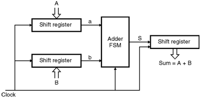
Let us consider A = an–1 an–2….a0 and B = bn–1 bn–2 ….b0 are the two unsigned numbers that has to be added to produce the sum S = Sn–1,Sn-2….So .
This addition process starts by adding bits a0 and b0 then in the next clock cycle bits a1 and b1 are added, which is also added with the carry from the bit position '0' and so on. In order to do this the input shift registers are loaded parallely with the values of bits is added by the adder FSM and at the end of the cycle the recounting sum bit shifted into the sum register.
Positive edge triggered flip flops are used in some cases in which all changes take place soon after the positive edge of the clock.
At this time the contents of all three-shift registers are shifted to the right this shifts the existing sum bit into sum bit into sum register and it presents the next pair of input bits ai and bi to the adder FSM.
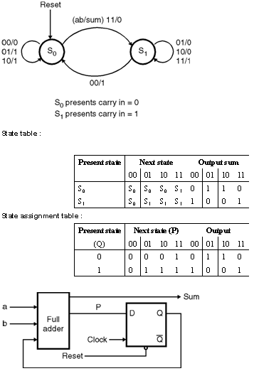
State diagram for serial adder :
Let S0 and S1 are the states where the carry in values is '0' and '1' respectively.
Figure shows the suitable state diagram defined as a mealy model.
The output value sum depends on both state and the present value of the inputs a and b, each transition is labeled using the notation ab / sum which indicates the value of sum for a given values of a and b.
In state so the values “ 00†will produce, sum = 0 and the FSM will remain in the same state for input values “01†and “10†the output will be sum = 1 and FSM will remain in S0. But for “ 11†Sum = 0 is generated and machine moves to state S1. In state S1 values “01†and “10â€causes sum = 0 while “ 11†causes sum = 1. In all three of these cases the machine remains in S1. However when the values 00 occurs the output of 1 is produced and a change into state S0 takes place.
Figure shows the corresponding state table for the state diagram. The state assignment can be done as indicated in state assignment table.
The assignment gives the following next state and output equations
P = ab + aQ + bQ
Sum = a  b  Q
The serial adder is a simple, circuit that can be used to add numbers of any length. The length of the adder is limited only by the size of the shift register.