Home > mini projects > AUTOMATIC RESISTANCE METER FOR 3 PHASE INDUCTION MOTOR DESIGN AND SIMULATION
AUTOMATIC RESISTANCE METER FOR 3 PHASE INDUCTION MOTOR: DESIGN AND SIMULATION
Abstract: Resistance calibration becomes important when induction motors is kept 'ON' for long interval.It is due to heating effect of electric current that resistance of coils no longer remains constant which in turn results in resistance variation. In industry the device can be of great help as it will auto adjust the resistance value according to variation in current.
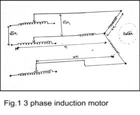
1] Introduction: An electrical motor is such an electromechanical device which converts electrical energy into a mechanical energy. These are self-starting induction motors which
works according to Faraday's law. It says that an emf induced in any circuit is due to the rate of change of magnetic flux linkage through the circuit. As the rotor windings in an
induction motor are either closed through an external resistance or directly shorted by end ring, and cut the stator rotating magnetic field, an emf is induced in the rotor copper bar and due to this emf a current flows through the rotor conductor.Here the relative velocity between the rotating flux and static rotor conductor is the cause of current generation.
When the motor is to be used after a long period of storage, it is important to measure the insulation resistances to ensure the seamless working of the motor. Also, if the motor is kept in moisturous conditions, periodically the resistances must be checked. Generally the ideal resistance is 10 Megohm or more.
|
Insulation |
Insulation level |
|
resistance value |
|
|
2 Megohm or |
Bad |
|
less |
|
|
5-10 Megohm |
Critical |
|
10-50 Megohm |
Abnormal |
|
50-100 Megohm |
Good |
|
>100 Megohm |
Excellent |
In this project, we have designed and simulated a device which measures the current through each coil and thus measures the resistances. Induction motors are most common motors used in any kind of Industry including it be an electrical or otherwise. For large operations 3-Phase Induction motors are employed and in such cases keeping track of insulation resistances is important.
2) CIRCUIT DIAGRAM
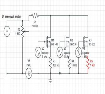
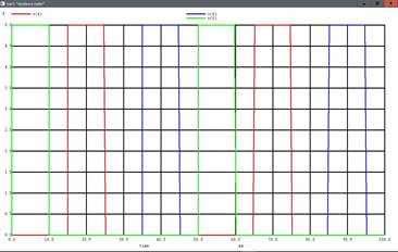
3 ] Overview of device design: Series type ohmmeter measures resistances across the windings one at a time. In this circuit, mosfets are used to switch between different resistances as load. Pulses are given in such a way that only one of the load resistances is measured at a time. Guard bands are given to facilitate seamless switching. Different insulation resistances are taken in loop for different interval and current across it is measured using D'arsonval's meter.
4) NETLIST: *Resistance meter*
.model MOSN NMOS
vin 1 0 dc 5
r2 3 2 100
r1 3 1 1Meg
rm 3 10 100
M1 2 5 7 7 MOSN
M2 2 4 8 8 MOSN
M3 2 6 9 9 MOSN
Vg1 5 0 pulse(0 5 0n 1n 1n 10m 50m) Vg2 4 0 pulse(0 5 15m 1n 1n 10m 50m)
Vg3 6 0 pulse(0 5 35m 1n 1n 10m 50m)
req1 7 0 100k
req2 8 0 10k
req3 9 0 1k
vdum 1 10 dc 0
.control
tran 0.5m 100m
run
plot v(5) v(4) v(6)
plot i(vdum)
.endc
.end
5) Input :
Output:
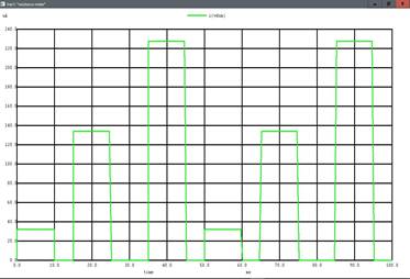
6)Results for current and resistance relationship:
We analysed the circuit with various load resistance and measured the current flowing through it. After manual analysis of the circuit, we utilised the 'ctool' of MATLAB for curve fitting. Hence we get the relation between current and load resistance of the circuit . A polynomial of degree 4 satisfies the relation, for any degree lower then this, curve does not fits well. This relation is used to determine the value of resistance using the current value.
In this project we present a device to measure resistance of 3 phase induction motor. On such application of voltages a guard band has to be maintained.

It is the time gap when no current flows while one switch is turned on and another switched off simultaneously. The device is simulated successfully on ngspice and its input and output graphs are plotted.