Home > mini projects > CMOS Based Analog Function Generator
CMOS-Based Analog Function Generator
![]()
Abstract - Modeling and Simulation of an analog function generator is presented by using basic CMOS circuit blocks. The proposed function generator model is based on a polynomial expansion model that uses a 10th order polynomial approximation of any of the required functions. In this project, a circuit model is proposed that can simultaneously generate many different mathematical functions. The circuit model is designed and simulated with NGSPICE and its performance is demonstrated through the simulation of a number of non-linear functions.
Index Terms - Analog function generator, CMOS NGSPICE models, NGSPICE simulation, Polynomial expansion modeling.
I. INTRODUCTION
Analog nonlinear circuits have many applications, especially in signal processing, communication, instrumentation, neural networks, and medical equipment. Earlier analog signal processors were designed with the use of passive electronic components such resistors and simple semiconductor devices such as diodes and BJT transistors. With the advantage of BJT and MOSFET transistors, the non-linear characteristics of these devices have then been exploited in the design of such processors. Many approaches of approximations of non-linear functions have been reported. So the use of BJT and Bi-CMOS transistors have been done to simulate non-linear functions.
More recently, CMOS analog circuits based on the exponential-law and the square-law characteristics of a CMOS transistor operating in weak and strong inversion respectively have been reported.
These circuit realizations present some disadvantages, the two most important being the realization of only one function at a time and their operation in voltage mode or mixed current and voltage mode. However, in current-mode circuits wider signal bandwidths and larger dynamic ranges of operation can be obtained as opposed to voltage-mode circuits.
A number of CMOS current-mode analog devices have been However, these circuits present many disadvantages such as their realization of only a few functions and only one function at a time In addition, these circuits are based on piecewise linear approximations of the non-linear functions.
The circuit based on a third order Taylor's series expansions of non-linear functions is previously been devised.
In this project, a CMOS-based circuit model of a analog function generator that can realize a large number of non-linear functions is presented. The circuit model is based on a 5th-order polynomial approximation of any non-linear function and is compatible with the CMOS technology currently used in digital signal processing. Another advantage of this model is the operation of the CMOS transistors in the strong inversion region, leading to the possible circuit operation at high frequencies.
II. PROPOSED CIRCUIT MODEL
In this circuit model, a 5th order polynomial of the form is used to approximate non-linear functions with a high degree of accuracy. In current mode, with the variable x representing the normalized input current, equation (1) can be realized by taking the sum of the multiplied output currents of a number of building blocks that consist of the traditional current mirror circuit to provide both power-raising and amplification of the current input, and adding it to a constant current.
The polynomial equation is
f(x)= a0* x0 + a1* x1 +a2* x2 + a3* x 3 + a4* x4+ a5* x5 (1)
One such building block is the squaring unit shown in Fig. 1 where Iin is the input current, Ib the bias current, and Iout is the output current. The aspect ratios (W/L) of transistors T1 - T8 of Fig. 1 are shown in Table I. The Transistors T1 and T2 as well as T3 and T4 are assumed to be well matched and transistors T1 through T8 are assumed to have the same value of the transconductance parameter i.e., βn = βp and are operating in their saturation region. With these assumptions, the translinear principle is applied to produce the output current I out which can be then expressed as [7].
![]()
(2)
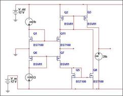
Fig. 1. Modified current mirror to the square of the input current.
TABLE I: W/L FOR THE CMOS
|
Transistor |
T 1 |
T 2 |
T 3 |
T 4 |
T 5 |
T 6 |
T 7 |
T 8 |
|
|
W/L |
1/ 1 |
1/ |
1/ |
1/ |
1/ |
1/ |
1/ |
1/ |
|
|
1 |
1 |
1 |
1 |
1 |
1 |
1 |
|||
In order to obtain a current proportional to x3, the following relation is used:
![]()
(5)
The corresponding circuit will therefore require two modified squaring circuits with inputs proportional to the difference and the sum of the input current and its square. The required third order term in (1) can then be obtained by selecting appropriate values of the W/L. In order to obtain output currents proportional to even and odd powers of the input current, the modified squaring circuit of along with equations are repeatedly used.
TABLE II: CURRENTS PROPORTIONAL TO ODD POWERS
|
x + x 2 and |
x + x 4 and |
|||
|
I in |
x - x 2 |
x - x 4 |
||
|
I 1 |
x 3 /2 |
x 5 /2 |
||
|
PROPORTIONAL TO EVEN POWERS OF |
||||
|
I in |
x |
x 2 |
||
|
I 2 |
x 2 /8 |
x 4 /8 |
||
![]()
It can therefore be concluded that higher-order terms of equation (1) can be obtained by repetitive use of the circuit model of Fig1 without the need for dedicated current multipliers. With this design and the addition of a normalized DC current, any function can be realized using MOSFET current-mirrors with the appropriate W/L. Fig. 3 shows the basic circuit model of the function generator where B refers to the squaring circuit model of Fig. 1. The circuit shows only outputs proportional to x through x6.
This circuit is advantage over the conventional one as only MOSFETs are which are lower power consuming device. But on the other hand the speed is compromised. The other advantage is it requires no passive elements.
III. SIMULATION RESULTS
The basic circuit models of Fig. 3 is used in the simulation of a number of functions. The corresponding polynomial expansion coefficients a i, i = 1, …, 4 for elected functions are given in Tables III, and the transistors' aspects ratios were selected accordingly. NGSPICE circuit simulator was used and the simulation was carried out using the MOSFET transistor models with L=0.1μm, bias current I b=.8μA and supply voltages VDD = -VSS = 2V.
The exact nonlinear function of ln(1-x) was calculated and their graphs compared with those of the simulated functions as illustrated in Fig. 4 . Inspection of these figures clearly shows that the simulated results are in agreement with the usually obtained graphs.
|
Function |
a0 |
a1 |
a2 |
a3 |
a4 |
|
ln(1-x) |
0 |
-1 |
-1/2 |
-1/3 |
-1/4 |
|
sinx |
0 |
1 |
0 |
-1/6 |
1/120 |
|
tanhx |
0 |
1 |
0 |
-1/3 |
2/50 |
Table III: Values of coefficient for polynomial.
|
Function |
sinx |
Tanhx |
ln(1-x) |
|
Range of x |
<1µA |
<1µA |
<0.9µA |
Table IV: Range of current values
The simulation result of ln(1-x) is being verified. All the functions can similarly be constructed.
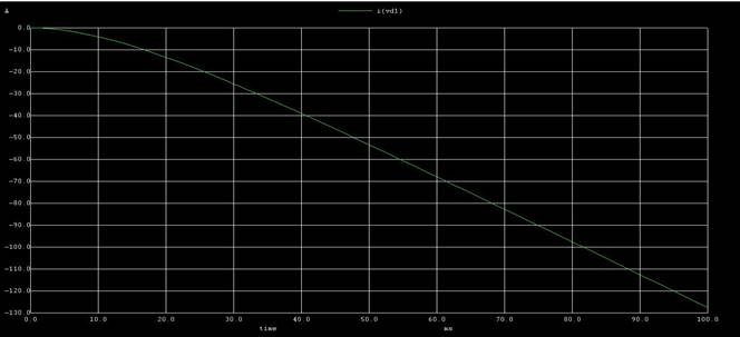
Fig4 The output waveform of the model
IV. CONCLUSION
Simulation of a simple function generator using MOSFET transistor models available in NGSPICE simulator has been presented. The circuit model was based on approximating any nonlinear function with the first 5 terms in its polynomial expansion. The circuit model that realizes any of these functions consists of power-factor raising circuits built around a basic current squarer circuit, a weighted current amplifier and a dc current source. The proposed simulation model can be easily modified to implement many functions by proper selection of the transistors' W/L ratio. The accuracy of the synthesized function will be primarily decided by the number of terms used in the power expansion approximation and the effects of mismatch between transistors used in practical implementation of the required current-mirrors. Expanding further the approximation requires the use of additional similar power- raising circuit blocks. Simulation of a number of nonlinear functions supported by the evaluation of the mean square error between exact and simulated functions values verified the validity of the proposed function generator circuit model.