Home > mini projects > FM TRANSMITTER
Abstract -
The transmission of input signals is achieved by the frequency modulation technique. This report demonstration of use of Hartley Oscillator for the generation of carrier signal's frequency and a tarnsistor for the modulation of the signal. Original signal is obtained back by demodulating the modulated signal by using rectifier detector.
INTRODUCTION
In telecommunication, frequency modulation transmits information by changing the frequency of carrier wave according to the instantaneous frequency of the message signal.
Carrier frequency is high compared to message frequency and it's range is in mega hertz to transmit and receive the FM signal.
Digital data can be encoded and transmitted via FM by using one frequency for logic 1 and different frequency for logic 0.
CIRCUIT DIAGRAM
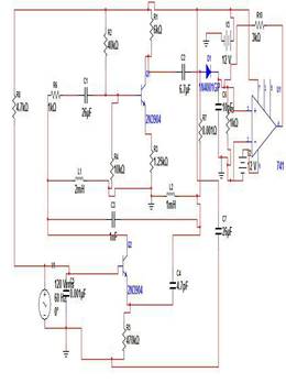
WORKING
Generally, a microphone is used to accept the sound signals.Inside the mic capacitive sensor diaphragm vibrates according to the air pressure changes and genarates ac signals.
The hartley oscillator is used to generate the carrier wave of frequency f.T he hartley oscillator consists of LC tank circuit.
The input signal is fed to the base of the transistor which modulates the hartley oscillator's carrier frequency in a FM format.
The variable capacitor is used to change the resonant frequency for fine adjustment of FM frequency band.
The fm modulated signal is send to the antenna.
For demodulation of signal the FM modulated signal is first converted to AM modulated signal.
The AM modulated signal is demodulated using rectifier detector.A rectifier detector consists of a diode and capacitor and a resistor in parallel.
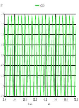
The demodulated signal is obtained and it is amplified.
The demodulated signal is amplified using non-inverting op-amp.
CODE
0PAMP SUBCIRCUIT
.subckt opamp 1 2 6
r1 1 2 10meg
e1 3 0 2 1 100k
r2 3 4 1k
c1 4 0 15u
e2 5 0 4 0 1
r3 5 6 10
.ends opamp
.include jop.cir
x 11 0 12 opamp
rb 1 2 1k
cc1 2 3 26u
r1 3 4 40k
r2 3 0 10k
vcc 4 0 dc 12v
rc 4 5 6k
.model bjt npn
q1 5 3 6 bjt
re 6 0 1.25k
cc2 5 7 6.7u
r8 7 0 6k
c1 1 7 1n
l1 1 0 2m
l2 0 7 1m
c3 7 9 4.7p
r3 9 0 470k
c4 8 0 0.001u
v1 8 0 sin(1 2 1K)
r4 4 8 4.7k
c5 4 0 22n
d1 7 10
c6 10 0 1u
r9 10 0 1k
ro 10 11 1k
rf 11 12 1.5k
.tran 10u 70m
.control
run
display
set color0=white
set color1=black
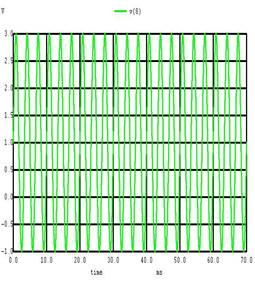
plot v(8) OUTPUT SIGNAL plot v(12)
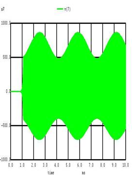
plot v(7)
.endc
.end
WAVEFORM
INPUT SIGNAL
CONCLUSION
MODULATED SIGNAL The modulated and demodulated output waveforms for different frequencies are
observed.By the use of variable capacitor in
hartley oscillator we can tune the signal to the
desired frequency.