Home > mini projects > Three Phase Inverter using MOSFET to drive BLDC motor and general three phase Load
Three Phase Inverter using MOSFET to drive BLDC motor and general three phase Load
Abstract -Inverters are a vital part of electric drive and industrial electrical infrastructure. They are used to drive BLDC and other 3 phase motors. This project presents the design and simulation of 3 phase power inverter.
I. INTRODUCTION
AC supply is the de facto standard for power generation and transmission. But certain devices designed for ac operation are intended to be run from stored electric energy. With the rising use of BLDC (Brushless DC) motors and other 3 phase motors in industrial and robotics applications, dc to ac conversion is highly desirable. This can be achieved using inverters. This project presents the design of a 3 phase inverter to drive BLDC motors and other general purpose 3 phase loads and its simulation in NGSPICE
II. Classes of inverters
Inverters are classified as pure sine wave and modified sine wave inverters. Pure sine wave inverters generate supply consisting of a single sinusoid. Such power source is needed for devices that require pure sine wave as input. Modified sine wave inverters generate output that consists of higher order harmonics along with the fundamental desired frequency. Loads such as motors can run on modified sine wave as the inductive load can suppress harmonics to a certain extent. BLDC motors can be directly driven from this inverter. If smoother waveform is desired, the output can be further filtered to suppress the harmonics and get a cleaner waveform.
A. Design of switching circuit.
The proposed design consists of 6 N channel MOSFETs that are switched in a particular order as described in a further section such that at any time 3 switches are closed. This creates a path consisting of 2 load phases in parralel with one phase in series to it at any time.Thus the voltage across any phase passes through the following levels.
0 V*1/3 V*2/3 V*1/3 -V*1/3 -V*2/3 -V*1/3 0
This constitutes a modified sine wave. To smoothen out the output further, filters are used. We have demonstrated this using a capacitive low pass filter to suppress higher harmonics to obtain a smooth output.
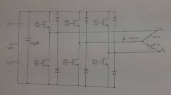
Fig. 1. Inverter circuit using MOSFETs
B. Control of switching logic
The timing diagram of switching logic is illustrated in the fig.
2. The logic for it can be implemented using a controller or simple digital/analog circuits to obtain a set of pulses with 60 degree phase shift between them. One cycle of the waveform corresponds to 6 switching steps. We have simulated the same in NGSPICE using pulses as inputs to the gates.
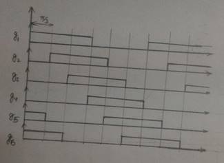
Fig. 2. Timing diagram for switching of MOSFETs' gates
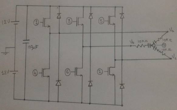
Fig. 3. Inverter with capacitive filter
C. Advantages of controlled switching.
Working of a number of electric machines is closely tied to the frequency of the supply. Speed of electric motors is controlled by varying the frequency of supply. Frequency of the sinusoid obtained using the proposed method can be easily varied by controlling the period of pulses used to control the gates of MOSFETs. Hence they can have an effective application in electric drives. The output obtained is capable of driving a BLDC motor. The angular velocity can be controlled by varying the rate of switching of the gates.
D. Using filters
The obtained waveform contains harmonics of the desired fundamental frequency. Hence a filter at output is highly desired to suppress those harmonics. This can be easily achieved using passive filtering components such as inductors and capacitors. We have implemented and simulated a first order capacitive filter (fig. 3) . The result is a better version of the output obtained without any filter.
III. Simulation Results
A. 3 phase inverter with Resistive load without using any filter.
When the load is purely resistive, a six step waveform is obtained (fig. 4). It can be used to drive a BLDC motor.
B. 3 phase inverter with capacitive filter.
A first order capacitive filter is used. Some of the harmonics are suppressed and a smoother waveform is obtained. Though the waveform is not purely sinusoidal, it has less harmonics compared to that without any filter. (fig. 5)
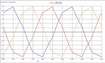
Fig. 5. Three phase inverter output with capacitive filter.
Fig. 6. Output across a single phase of the three phase
inverter with capacitive filter