Home > mini projects > Zero Crossing Detector
Abstract - In this era, we are surrounded by various electrical equipments which are in turn controlled by the ac signal. Thus, it is essential to study the properties of these signals so that we can extract information from them and manipulate them. Zero Crossing Detector Circuit is one such example through which we can explore the attributes of ac signal.
II. CIRCUIT DIAGRAM:
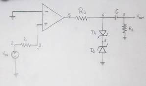
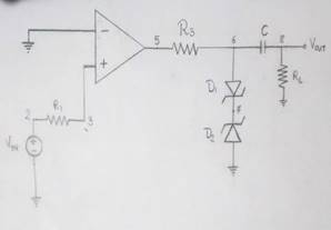
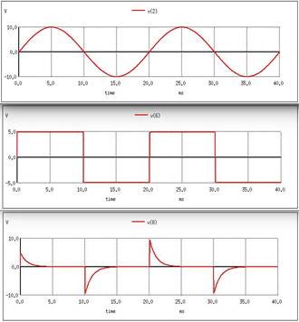
1. Ideal ZCD circuit for ideal input -
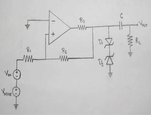
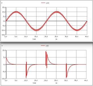
2. Ideal ZCD circuit for noisy input -
I. INTRODUCTION:
A Zero Crossing Detector (ZCD) is a type of voltage comparator, with the reference level set to zero volts. It is used for detecting the zero crossings of an ac signal, i.e. transition from positive half cycle to negative half cycle or negative half to positive half cycle in the input signal.
It can be made using operational amplifier i.e. opamp, with input voltage fed to one terminal of opamp and zero volts applied to another. In this project, we are going to use opamp as a
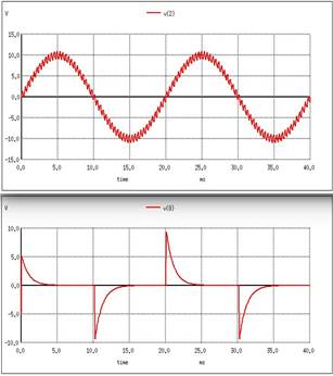
ZCD for detecting transition of sinusoidal wave 3. Practical ZCD circuit for noisy input -
(Vpp = 20V) from positive half to negative half and vice-versa. We will be exploring the difficulties involved in implementing a practical ZCD due to interference of noise and other factors in the original signal. We will also see how to accurately determine the zero crossings in the practical circuit.
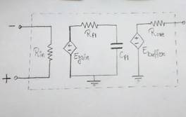
1) OPAMP: An operational amplifier (OPAMP) is a DC Coupled high gain electronic voltage
amplifier with a differential input and single ended output. It is an active device. The magnitude open loop gain is
very large in the order of 105 and hence even a small difference between the two terminals drives the output voltage nearly to supply voltage.
2) Zener diode: Zener diode or breakdown diode is specially designed pn junction diode which have a low predetermined reverse breakdown voltage reverse breakdown voltage that takes advantage of this high reverse voltage. Zener diode is the simplest type of voltage regulator and the point at which zener diode breaks down or conducts is called "Zener voltage".
1. Ideal ZCD circuit for ideal input -
2. Ideal ZCD circuit for noisy input -
3. Practical ZCD circuit for noisy input -
V. WORKING:
1. OPAMP is used as comparator. When input
voltage at non-inverting terminal is greater than zero, positive output voltage(Vp) is obtained. And when it is less than zero, negative output voltage(Vn)is obtained.
2. Due to zener voltage regulator, the output voltage levels are as follows:
Vp = VfD1 + VzD2 Vn = VzD1 + VfD2
3. RC circuit gives positive and negative impulses at every transition of output levels.
4. In case of practical zero crossing detector(noise added), R2 is used as positive feedback which changes the positive threshold (Vth+) and negative threshold (Vth-) to
Vth+ = -Vn*R1/R2 Vth- = -Vp*R1/R2
VI. CONCLUSION:
1. Zener voltage regulator gives smooth square wave as Output, which is then passed through RC circuit that gives alternate positive and negative Impulses.
2. In case of practical zero crossing detector(noise added),two threshold values are obtained. By choosing thresholds separated by a voltage larger than the noise,the comparator's output produces a nice and clean squarewave.