Asynchronous counters called ripple counters, the first flip-flop is clocked by the external clock pulse and then each successive flip-flop is clocked by the output of the receding flip-flop. The term asynchronous refers to events that do not have a fixed time relationship with each other. An asynchronous counter is one in which the flip-flops within the counter do not change states at exactly the same time because they do not have a common clock pulse.
2-Bit Asynchronous Binary Counter
Operation:
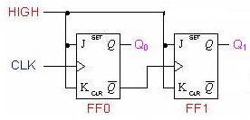
A 2-Bit Asynchronous Binary Counter Fig1-1 shows a 2-bit counter connected for asynchronous operation. Notice that the clock (CLK) is applied to the clock input (C) of only the first flop-flop, FF0, which is always the least significant bit (LSB). The second flip-flop, FF1, is triggered by the ̅Q0 out-put of FF0.FF0 changes state at the positive-going edge of each clock pulse. But FF1 changes only when triggered by a positive-going transition of the ̅Q0 output of FF0. Because of the inherent propagation delay tie through a flip-flop, a transition of the input clock pulse (CLK) and a transition of the ̅Q0 output of FF0 can never occur at exactly the same time . Therefore, the two flip-flops are never simultaneously triggered, so the counter operation is asynchronous.
Timing Diagram
Applying 4clock pulses to FF0, Both flip-flops are connected for toggle operation (J=1, K=1) and initially RESET (Q LOW). The positive-going edge of CLK1 (clock pulse1) causes the Q
0 output of FF0 to go HIGH. At the same time the ̅Q0 output goes LOW, but it has no effect on FF1 because a positive-going transition must occur to trigger the flip-flop. After the leading edge of CLK1, Q0=1 & Q1=0. The positive-going edge of CLK2 causes Q0 to go LOW. ̅Q0 goes HIGH and triggers FF1, causing Q1 to go HIGH. After the leading edge of CLK2, Q0=0 & Q1=1.
The positive-going edge of CLK3 causes Q0 to go HIGH again. Output ̅Q0goes LOW and has no effect on FF1. Thus, after the leading edge of CLK3, ̅Q0=1 & Q1=1. The positive-going edge of CLK4 causes Q0 to go LOW, while ̅Q0 goes HIGH and triggers FF1, causing Q 1 to go LOW. After the leading edge of CLK4, Q0=0 & Q1=0. The 2-bit counter exhibits four different states, as you would expect with two flip-flops (22= 4). The fourth pulse it recycles to its original state (Q0=0, Q1=0). The term recycles; it refers to the transition of the counter from its final state back to its original state.

3-Bit Asynchronous Binary Counter
It works exactly the same way as a two-bit asynchronous binary counter mentioned above, except it has eight states due to the third flip-flop.
