One common application of the Uni junction transistor is the triggering of the other devices such as the SCR, triac etc. The basic elements of such a triggering circuit are shown in figure below. The resistor RE is chosen so that the load line determined by RE passes through the device characteristic in the negative resistance region, that is, to the right of the peak point but to the left of the valley point, as shown in figure. If the load line does not pass to the right of the peak point P, the device cannot turn on.
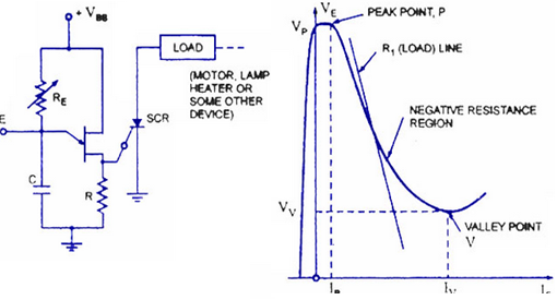
For ensuring turn-on of UJT
RE < VBB – Vp / IP
This can be established as below Consider the peak point at which,
IRE = Ip and VE = VP
the equality IRE = IP is valid because the charging current of capacitor, at this instant is zero, that is, the capacitor, at this particular instant, is changing from a charging state to a discharging state.
Then,
VE = VBB – IRE RE
RE (MAX) = VBB – VE¬ / IRE = VBB – Vp / IP
At the valley point, V
IE = IV and VE = VV so that
VE = VBB – IRE RE
So RE (MIN) = VBB – VE / IRE = VBB – VV / IV or
for ensuring turn-off.
RE > = VBB – VV / IV
So, the range of resistor RE is given as
VBB – VP / IP >RE > VBB – VV / IV
The resistor R is chosen small enough so as to ensure that SCR is not turned on by voltage VR when emitter terminal E is open or IE = 0
The voltage VR = RVBB/R + RBB for open-emitter terminal. The capacitor C determines the time interval between triggering pulses and the time duration of each pulse. By varying RE, we can change the time constant RE C and alter the point at which the UJT fires. This allows us to control the conduction angle of the SCR, which means the control of load current.
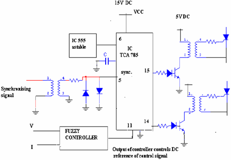
Triggering Circuit by Synchronized UJT & IC 785
IC TCA 785 a 16 pin IC shown in figure is used in this study for firing the SCRs. This IC having output current of 250 mA and a fuzzy logic trainer kit with two input variables and having 5 linguistic sets is used. This can generate 5 X 5 rules. The output of fuzzy logic which varies from DC -10V to +10V is given to IC 785 controller pin11, which controls the comparator voltage VC ,and the firing angle α for one cycle and (180 +α) during negative cycle shown in figure.