Home > Analog CMOS Design > MOSFET Fundamentals > Saturation Region of Operation
Saturation Region of Operation :
When we increase the drain to source voltage further the assumption that
the channel voltage is larger than the threshold all along the channel does
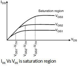
not hold and the drain current does not follow the parabolic behaviour for
VDS > VGS - VTH as shown in
Figure below. In fact as shown in Figure IDS becomes relatively
constant and the device operates in the saturation region.
In order to understand the phenomenon of saturation consider the Equation (8.3.6) again which is given as :
Qi (x) = - Cox [VGS - V (x) - V TH]
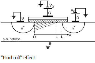
i.e. Inversion layer charge density is proportional to (VGS - V (x) - VTH). Thus if V (x) approaches VGS - V TH then Qi (x) drops to zero. In other words as shown in Figure below if VDS is slightly greater than VGS - VTH then the inversion layer stops at x £ L and we say that the channel is 'pinched off'.
As VDS increases further the point at which Qi (x) equals zero gradually moves towards the source. Thus at some point along the channel the local potential difference between the gate and the oxide silicon interface is not sufficient to support an inversion layer.
Therefore for saturated device the integral limits on the left hand side of
the
Equation (8.3.13) must be taken from x = 0 to x = L¢, where L¢ is the point
at which Qi (x) drops to zero and that on the right side from V
(x) = 0 to V (x) = VGS - VTH.
As a result of Integration we get,
IDS = mn Cox (VGS - V TH)2 …(8.3.21)
The above equation of IDS indicates that IDS is
independent of VDS if L¢ remains close
to L.