Inverting adder:
The input signals to be added are applied to the inverting input terminal of op-amp. The following figure shows the inverting adder using op-amp with two inputs V1 and V2.
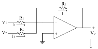
Let us assume currents I1 and I2 are flowing through resistances R1 and R2 respectively. Since input current to the op-amp is zero, the two currents are added to get current I, which flows through the feedback resistance Rf.
Thus by KCL at inverting terminal, we get

Substituting for the currents,
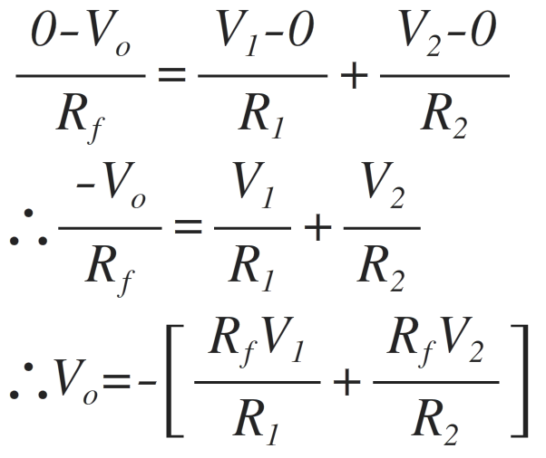
Thus the above equation gives the weighted addition of the two input signals (in the form mX + n Y, where m and n are the weights of inputs X and Y respectively)
If R1=R2=R
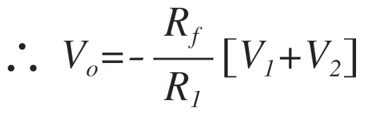
Thus the addition of the two input signals obtained with gain [-Rf/R ]
If Rf=R,
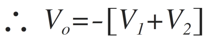
Thus the addition of two inputs obtained. The negative sign indicates that input and output are having 180̊ phase shift.
The above circuit can also be used to get the average of the two inputs, with the following substitution. Thus the circuit can be used as an averager.
If R=2Rf

Non-inverting adder:
The input signals to be added are applied to the non-inverting input terminal of op-amp. The following figure shows the non- inverting adder using op-amp with two inputs V1 and V2.
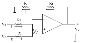
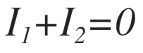
Let us assume currents I1 and I2 are flowing through resistances R1 and R2 respectively. Since input current to the op-amp is zero, the addition of the two currents is zero at non-inverting terminal.
Let the non-inverting terminal is at potential 'V'. Due to virtual ground concept, the inverting terminal appears to be at the same potential 'V'.
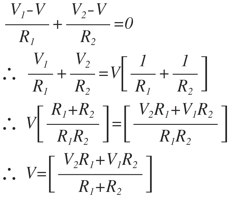
Thus by applying KCL at non-inverting terminal we get,
Substituting for the currents, we get
The current 'I' from the feedback path is given as,
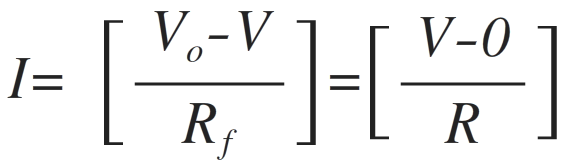
Solving the above equation for Vo, we get
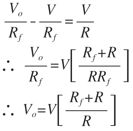
Substituting voltage 'V' from equation (1) in above Vo equation
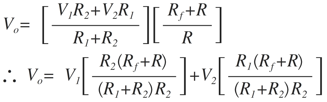
If R1=R2=R=Rf
∴Vo=V1+V2