By Exchanging the positions of 'R' and 'C' in integrator the differentiator circuit is obtained
The circuit which produces the differentiation of the input voltage at its output is called differentiator.
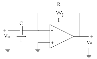
The following circuit diagram shows the differentiator using op-amp.

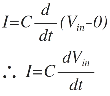
Assume current 'I' is flowing through capacitor C. It is given as
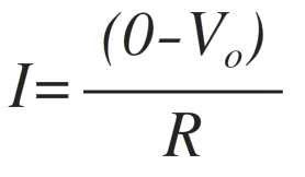
Since input current to the op-amp is zero, same current 'I' flows through resistance R as shown. It is given by
Equating both the above equations of 'I' we get,
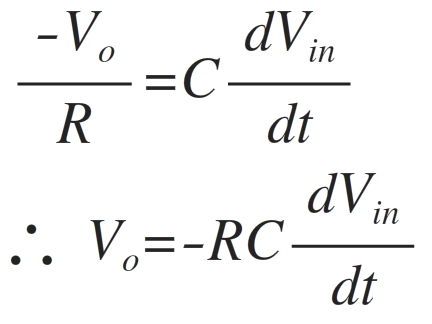
Thus output voltage is nothing but time differentiation of the input signal and hence acting as differentiator. Here 'RC' is the time constant of the differentiator.
Now let us see what is the response of the differentiator to the different types of input signals.
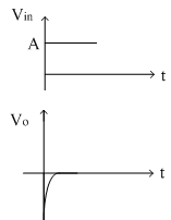
1)Vin = Step signal
The step signal is defined as follows
Vin (t)=A for t>0
Let the product RC = 1.
The output voltage is given as
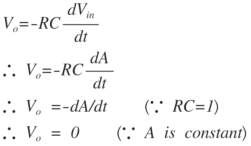
Practically the step input is taking some finite time to rise from 0 to magnitude A. Due to this small interval of time, the differentiator output is not zero; but appears in the form of spikes at t = 0. The input and output waveform is shown below.
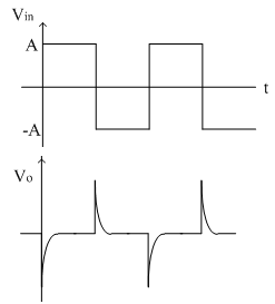
2)Vin = Square Wave
The square wave is nothing but combination of positive and negative step signals. As seen in first case, the output of step signal is a spike. For positive step signal, a negative spike is obtained because it is inverting differentiator. Thus for a square wave input, the output obtained is a spike waveform as shown in figure below.
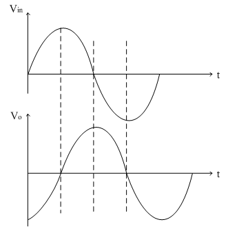
3)Vin = Sine Wave
Let Vin=Vm sinωt
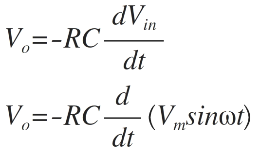
Assuming the time constant RC = 1 and taking the differentiation, we get
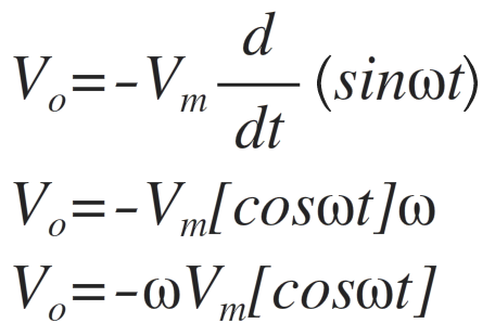
Thus the cosine wave is obtained as shown below.
Frequency response of ideal differentiator:
The ideal differentiator using op-amp is shown below.
The voltage gain for the same is given as

The magnitude of gain A is
|A|=|2πfRC|
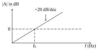
Thus the gain A is directly proportional to frequency f.
At low frequency, the gain is also low. As frequency increases, gain also increases linearly at the rate of 20dB/decade. For dc input (f = 0) the gain is zero.
Let, the frequency fa is defined as follows
fa=1/2πRC
Therefore the gain A is given as
|A|=|f/f_a |
Thus When f < fa, the gain A is less than 1( i.e. negative)
When f = fa, then the gain is 1 (i.e. 0dB)
Thus the frequency fa is nothing but the 0 dB (or unity gain) frequency for differentiator.
When f > fa, the gain A is increases linearly at the rate of 20dB/decade.
The frequency response of ideal differentiator is shown in figure below.
Disadvantage of ideal differentiator:
The reactance of the capacitor Xc is given as Xc=1/2πfC
As frequency increases, Xc reduces i.e. Capacitor draws more current from input source. Thus at high frequency input source gets loaded by capacitor C. Therefore noise signals at higher frequency gets amplified and appeared at output. So to avoid the mis-amplification of the signal the ideal differentiator is modified and referred as practical differentiator or compensated differentiator.