Home > mini projects > A statistical comparison of binary weighted and R 2R 4 Bit DAC
A statistical comparison of binary weighted and R-2R 4 Bit DAC's
Abstract- A statistical comparison of the 4-bit binary weighted and R-2R digital-to-analog converters have been made in this project which helps us to get a better idea as to which of the DAC is to be selected for the given specified application. Also, a radiant approach has been taken to increase the performance of both the DACS' with respect to the performance of the existing practical DACS'
Index Terms- digital-analog conversion, operational amplifiers, binary weighted DAC,ladder circuits.
I. INTRODUCTION
D igital to analog convertors are used thousands of times in our daily life. Connecting digital circuitry to sensor devices is simple if the sensor devices are digital. Even in communication system, digital transmission is faster and convenient but the digital signals should be converted back to analog signals at the receiving terminal. So, whenever we are in the need of conversion of a digital to analog signal, we are to look up to these DACs. A simple example of it is a conversion of computer data into Audio-Frequency tones need for telephony.
.Analog signals are those in which the values are continuous in time and amplitude domains and in digital signals are those in which the values are discrete in time and amplitude domains .If a signal is to be stored and processed it is not feasible in analog form. It is to be converted into digital format. So, whenever we are in the need of conversion of a digital to analog signal, we are to look up to these DACs.
Now, in this project, we are talking mainly about the performance and various improvements that have been done in the 4-bit binary weighted and R-2R ladder DACs .So, having a brief introduction on both of these DACs is as follows:
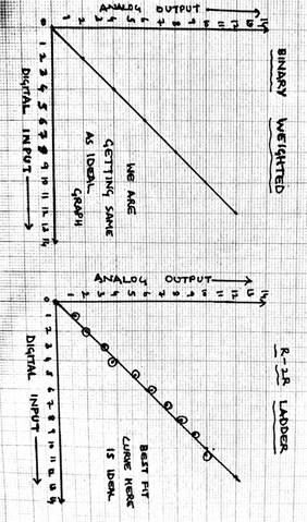
1.Binary Weighted Resistors : The binary weighted resistors DAC consist of 4 switches, one for each bit applied to the input. The resistors for the binary weighted DAC are inversely proportional to the numerical significance of the corresponding binary digital.
Working :
A reference voltage(5v) and a summing amplifier is used that adds current flowing to the resistive network. The current that flows can develop a signal that is proportional to its digital input with the help of operational amplifier. For logic '0', 0 volts is applied and for logic '1', 5 volts is applied at the input. By the principle of superposition, the output voltage equation can be obtained as shown.
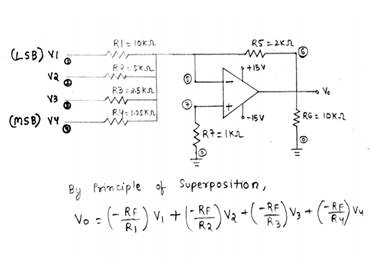
Figure for binary weighted DAC
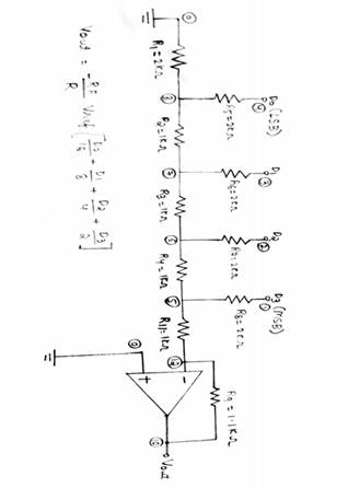
2. R-2R Ladder Resistor circuit: An alternative to the binary weighted input DAC is the R-2R Ladder, which uses fewer unique resistor values thus does not require precision resistors.
In the circuit D0 is the least significant bit while D3 is the most significant bit.
Working :
For logic '0', 0 volts is applied and for logic '1', 5 volts is applied at the input. The operational amplifier produces the output voltage for the corresponding digital input. By applying kirchoff's voltage and current laws. The output voltage equation can be obtained as shown.
OUTPUT WAVEFORMS("0011")
R 2R LADDER DAC
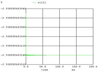
figure for R-2R ladder circuit
In practice, the converters' differences from an ideal behavior are characterized by a number of performance specifications that determine the DAC performance. Different applications have different performance requirements. To preserve the sound quality in audio, for example, the target is to have a high dynamic range with little or no distortion. For video systems, instead, the DAC linearity is the crucial parameter to ensure systems harmonic a good picture quality. Hence selecting the right DAC for a particular application needs the knowledge of the performance requirements.
BINARY WEIGHTED DAC
Performance specifications:
Resolution
Resolution is defined as the number of different analog output voltage levels that can be provided by a DAC. Or alternatively resolution is defined as the ratio of a change in output voltage resulting for a change of 1 LSB at the digital input. The higher is the number of bits, the smaller is the analog (voltage or current) output step that could be output level generated and better it is for accuracy. An N-bit resolution implies producing 2N distinct analog levels.
Linearity error is the maximum deviation in step size from the ideal step size. Some D/A converters are having a linearity error as low as 0.001% of full scale. The linearity of a D/A
converter is defined as the precision or exactness with which the digital input is converted into analog output. An ideal D/A converter produces equal increments or step sizes at output for every change in equal increments of binary input.
Full scale range:
The Full scale range value for the R-2R ladder circuit DAC is 14.69V.
The Full scale range value for the Binary weighted DAC is 15V.
Accuracy:
Absolute accuracy is the maximum deviation between the actual converter output and the ideal converter output. The ideal converter is the one which does not suffer from any problem. Whereas, the actual converter output deviates due to the drift in component matching aging, noise and other sources of errors.
4-Bit Digital to Analog Converter using R-2R ladder circuit:
|
Input |
Ideal (V) |
Actual (V) |
Percentage Error (%) |
|
0000 |
0.00 |
0.00 |
---- |
|
0001 |
-1.00 |
-0.7491 |
1.800 |
|
0010 |
-2.00 |
-1.9425 |
2.800 |
|
0011 |
-3.00 |
-2.9137 |
2.867 |
|
0100 |
-4.00 |
-3.816 |
2.800 |
|
0101 |
-5.00 |
-4.8562 |
2.640 |
|
0110 |
-6.00 |
-5.8992 |
2.267 |
|
0111 |
-7.00 |
-6.7987 |
2.286 |
|
1000 |
-8.00 |
-7.77 |
2.800 |
|
1001 |
-9.00 |
-8.74126 |
2.822 |
|
1010 |
-10.00 |
-10.6887 |
6.880 |
|
1011 |
-11.00 |
-10.6837 |
3.1600 |
|
1100 |
-12.00 |
-11.655 |
1.833 |
|
1101 |
-13.00 |
-13.5975 |
4.5946 |
|
1110 |
-14.00 |
-13.860 |
2.360 |
|
1111 |
-15.00 |
-14.860 |
2.152 |
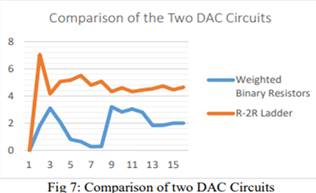
The percentage error graph for practical DACs is taken from the internet and is as:
Signal-to-Noise Ratio (SNR):
This is the ratio of the amplitude of the analog output of the DAC when the output is set to full-scale to the amplitude of the output when it is set to zero.
Glitch Impulse :
Glitch impulse may be defined as the impulse produced in between when there is a change in voltage level at the output due to change in input bits: The graph for the glitch obtained through the simulations is as follows:
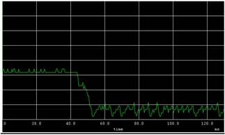
Thus, it is clear from all the above graphs that the output obtained from the now created circuit is by far better than that of the ones used normally.
Conversion Time:
It is the time taken for the D/A converter to produce the analog output for the given binary input signal. It depends on the response time of switches and the output of the Amplifier. D/A converters speed can be defined by this parameter. Theoritically, while performing the simulations on the ngspice ,we get the conversion time to be almost zero due to the fact that the variation in temperature, noise and other such parameters can't be included in such experimentation. Conversion time is also called as setting time.
Stability:
The ability of a DAC to produce a stable output all the time is called as Stability. The performance of a converter changes with drift in temperature, aging and power supply variations. So all the parameters such as offset, gain, linearity error & monotonicity may change from the values specified in the datasheet. Temperature sensitivity defines the stability of a D/A converter.
Input Leakage Current, I IL:
This is maximum leakage current exhibited by a digital input at logic "0".From the simulation graphs, the input leakage current for the binary weighted is 0 volts.
The observed input leakage current for both the circuits is 0 volts.
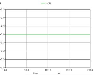
![]()
Here, in the above graph, the voltage is getting changed from 3v to 1v due to change in the input from 0011 to 0001.
Advantages of binary weighted circuit :
Simple and fast
Susceptible to noise
Advantages of r-2r weighted circuit :
Only 2 resistor values are required(R and 2R)
Does not require high precision resistors
Easy to manufacture
Disadvantages of binary weighted circuit :
In case of high resolution DACs large difference in resistor values is required between MSB and LSB and so not preferable
For example in case of 12 bit high resolution DACs if MSB is 1kohm then LSB needs to be 2Mohms
It is difficult to manufacture resistors over a wide range of resistances that maintain an accurate ratio especially whn there are variations in temperature.
Also, this is very expensive
Disadvantages of r-2r circuit :
Lower conversion speed than binary weighted DAC
CONCLUSION:
In view of Cost of hardware, R-2R DAC is better than Binary weighted. It is because in case of binary weighted DAC a wide range of resistances are required which makes it more expensive as compared to R 2R.
Now, on comparing stability with respect to temperature variations in the surroundings, R-2R is stable than Binary weighted DAC as binary weighted DAC requires large range of resistors whose resistance values may change with variation in temperature
R-2R DAC is more accurate when compared to Binary weighted DAC as obtained from the graph above. As per the simulations done on ngspice and multisim it is clear that the percentage of error is greater in case of binary weighted than in R-2R DAC. Thus , whenever accuracy is preferred,
Speed :
Binary weighted is faster compared to R 2R DAC.So, it means that the conversion time for R-2R ladder DAC is more as compared to that of binary weighted DAC.
Frequency Applications:
In high frequency applications, binary weighted DAC is advisable and preferred over other DACs. This being because binary weighted DAC has a very less conversion time with respect to R-2R ladder circuit DAC.