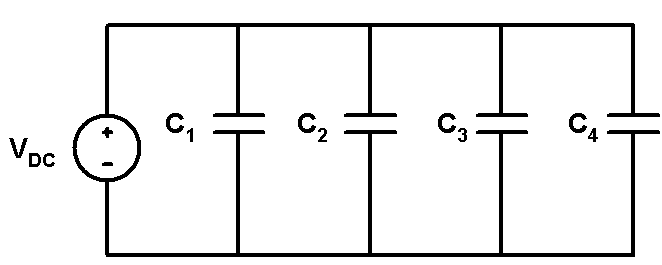
When the two terminals of the capacitors are connected to each other, then that combination of capacitors is called as the parallel combination of the capacitors. In parallel combination the supply voltage terminals are also connected to the parallel connected nodes of the capacitors. Since the supply voltage VDC is connected across all the parallel connected capacitors, the voltage drop across each capacitance is same. The parallel combination of the capacitors C1, C2, C3 and C4 is shown in figure bellow.
For Capacitor C1, voltage across the capacitor is V1, charge stored in the capacitor is Q1 and the current through the capacitor is I1.
For Capacitor C2, voltage across the capacitor is V2, charge stored in the capacitor is Q2 and the current through the capacitor is I2.
For Capacitor C3, voltage across the capacitor is V3, charge stored in the capacitor is Q3 and the current through the capacitor is I3.
For Capacitor C4, voltage across the capacitor is V4, charge stored in the capacitor is Q4 and the current through the capacitor is I4.
As we know that, in parallel combination the voltage across the capacitor is same in all the components. Hence the voltage applied in the circuit of parallel combination of capacitors is same across each capacitor. Therefore,
![]()
As shown in above figure, in parallel combination of capacitors, top side electrode of the first capacitor, C1 is connected to the top side electrode of the second capacitor, C2, top side electrode of the third capacitor, C3 and top side electrode of the forth capacitor, C4. Also the bottom side electrode of the first capacitor, C1 is connected to the bottom side electrode of the second capacitor, C2, bottom side electrode of the third capacitor, C3 and bottom side electrode of the fourth capacitor, C4. Further, the positive terminal of DC battery is connected to the top side electrode node combination and negative terminal of DC battery is connected to the bottom side electrode node combination of the capacitors. When the capacitors are connected in parallel combination the equivalent capacitance, Ceq in the circuit is equal to the sum of capacitance values of all the capacitors. For n capacitors connected in parallel the the equivalent capacitance of the combination is given by,
![]()
Now, the charging current flowing through the individual capacitances C1, C2, C3 and C4 are related to the voltage across the each capacitors, Therefore, the charging currents of the capacitors are given by,

By applying Kirchoff’s Current Law ( KCL ), to parallel combination circuit shown in figure above we get,
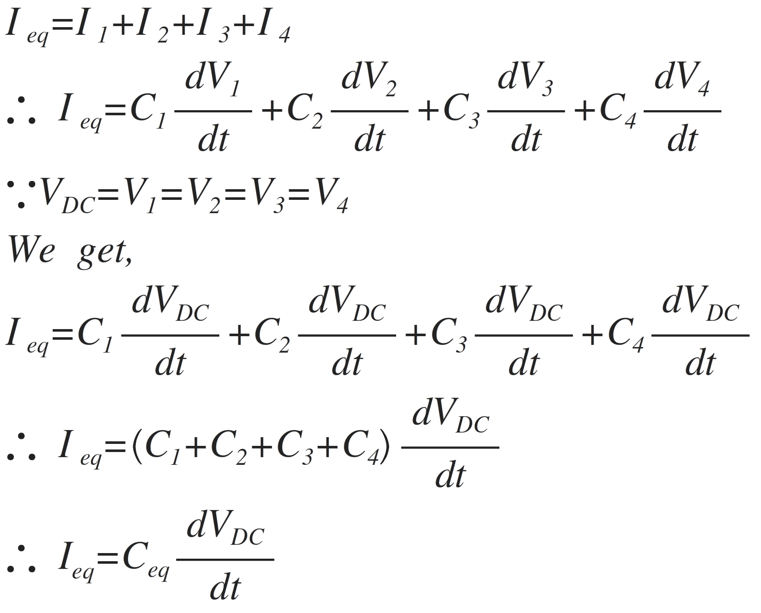
Thus, from above equation it can be seen that, the equivalent capacitance of the parallel combination of the capacitors is the sum of the individual capacitance values of the capacitors connected in parallel combination. Therefore, the equivalent capacitance of the parallel combination of capacitors is given by,
![]()
In parallel combination of capacitors when we add the individual values of the capacitors, the capacitance values which we need to be added should have same capacitance units. Hence if the individual capacitances values are having the units such as micro Farad, nano Farad, pico Farad or Femto Farad, then the capacitances units should be converted into the common unit.
The equivalent capacitance of the parallel combination can also be calculated by using the charge, capacitance and voltage equation of the capacitor. i.e. Q = CV
As we know that, the equivalent charge QEq stored in the equivalent capacitance of the parallel combination of the capacitors can be calculated as,
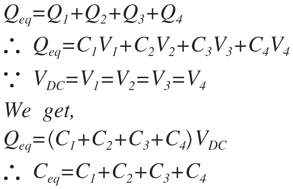
As in parallel combination of capacitances the capacitance are added together, the equivalent capacitance of the parallel combination increases.