Home > mini projects > Design and Modelling of Notch Filter using Universal Filter FLT U2
Design and Modelling of Notch Filter using Universal Filter FLT-U2
Abstract -The design of Notch filter, in this case, requires the implementation of nested sub-circuits of Op-Amp and FLU-U2 universal filter. This project is completely based on modelling software Ng-Spice. The circuits are designed/drawn in NI Multisim software.
INTRODUCTION
A band-stop filters or band-reject filters are filters the pass most frequencies unaltered, but attenuate the specific range of frequency. When this range of frequency is narrow, that band-reject filter is called as NOTCH filter. They are essentially the inverse of band-pass filters, which pass only a specific range of frequency
and attenuate/reject all other frequencies.
Few applications of Notch filter are in Raman spectroscopy, live sound reproduction systems and audio instrument amplifiers prevent audio feedback, laser or optical data links, Li-Fi, etc.
Universal filter FLT-U2 is used to implement this Notch filter.
UNIVERSAL FILTER (DATEL FLT-U2)
FLT-U2 is an active universal filter. It uses state variable active filter principle to implement a second order transfer Function. There are three operational amplifiers that are used for the second order transfer function, namely High-pass filter output, Band-pass filter output and Low-pass filter output. The fourth uncommitted amplifier can be used as gain stage, buffer, summing amplifier or add another independent pole in the transfer function.
By proper selection of external components, any filter like Low-pass, High-pass, Band-pass, Band-reject, Butterworth, Bessel, Chebyshev or Elliptic.
MATH
Equations
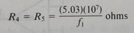
This equation is used to calculate the value of resister R4 and R5 for the external components.
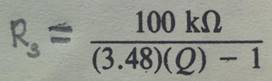
This equation is specified in the data sheet for calculating the value of R3.
The value of R2 is given as 100k.
As no extra gain is required in the filter, the feedback and input resistances of uncommitted op-amp are used as summing amplifiers and must be of equal value.
R6 = R7 = R8 = 10k
R8 = (R6||R7||R8) = 3.3k.
Notch Frequency= [1/(2Ï€RC)]
R is the equivalent series resistance of internal and external circuit and C is the internal capacitance of the FLT-U2. As C is fixed, the frequency of Notch controlled by changing the value of R.
For the modeling, the specifications considered are :
F = 20kHz
and Q = 10.
Design
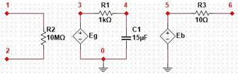
The Operational Amplifier designed as follows:
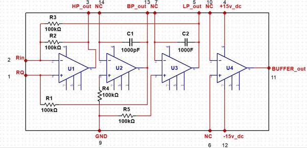
Using this model of Op-Amp, FLT-U2 is designed:
And finally this FLT-U2
 and the external components makes up the NOTCH filter:
AC analysis was performed on this Notch circuit to obtain the desired frequency response according to the specifications.
*SUB-CIRCUIT OF OPERATIONAL AMPLIFIER
.subckt opamp 1 2 6
Rin 1 2 10meg
e1 3 0 2 1 100k
r1 3 4 1k
c1 4 0 15u
e2 5 0 4 0 1
Rout 5 6 10
.ends opamp
*SUB-CIRCUIT OF UNIVERSAL FILTER FLT-U2
.subckt FLT-U2 1 2 3 14 13 7 5 10 11 6 9
.include OA.cir
X1 2 1 3 opamp
X2 14 40 13 opamp
X3 7 41 5 opamp
X4 10 6 11 opamp
R20 2 5 100K
R19 2 3 10K
R18 1 13 100K
R17 40 9 100K
R16 41 9 100K
C10 14 13 1000pF
C9 7 5 1000pF
.ends FLT-U2
*CIRCUIT OF NOTCH
.include UniFil.cir
X1 1 0 3 14 13 7 0 10 11 6 0 FLT-U2
R2 1 20 100K
R3 1 0 2.96K
R4 3 14 10.06K
R5 7 13 10.06K
R6 20 10 10K
R7 13 10 10K
R8 10 11 10K
R9 6 0 3.3K
Vin 20 0 ac
.ac dec 10 0 100meg
.control
run
display
SET COLOR0=WHITE
SET COLOR1=BLACK
SET xbrushwidth=3
**plot (-Vm(13)/Vm(20))
plot -Vm(11)/Vm(20)
.endc
.end
OUTPUT
Diagram
Results of ac analysis of Notch filter.
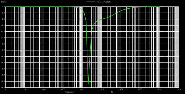
RESULT
A notch was obtained at 20kHz as observed on the output frequency response. Thus the notch filter design was modelled using NG-spice software.