Home > VHDL > Advanced VHDL > TestBench
Test Bench :
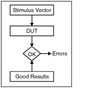
The test bench is used test the functionality of the in design under test. The test bench gives the necessary input stimulus to the design under test and examines the output from the design under test. Figure shows block diagram of the testbench process. The stimulus driver drives inputs into the design under test. The design under test works on input signals and produces output results. Finally, compare function within the test bench compares the results from the design under test. There are a number of methods for writing the test bench. However, each method has advantages and disadvantages. The different ways to write a test bench are,
 Stimulus only : Contains only the stimulus
driver and design under test.
Full test bench : Contains stimulus driver,
good results, and results for comparison.
Simulator specific : Test bench is written in a
simulator-specific format.
Hybrid test bench : Combines techniques from
more than one test bench style.
Fast test bench : Test bench written to get
ultimate speed from simulation.
To show the different types of
test benches, a common example is used.
To make it simple to understand
the stimulus and response, a counter example is used.
Stimulus only : Contains only the stimulus
driver and design under test.
Full test bench : Contains stimulus driver,
good results, and results for comparison.
Simulator specific : Test bench is written in a
simulator-specific format.
Hybrid test bench : Combines techniques from
more than one test bench style.
Fast test bench : Test bench written to get
ultimate speed from simulation.
To show the different types of
test benches, a common example is used.
To make it simple to understand
the stimulus and response, a counter example is used.
GENERIC MAP( mode => minimum,
                                 delay_tab => ((1.3 ns, 1.9 ns),
                                 delay_tab => ((2.1 ns, 2.9 ns),
                                 delay_tab => ((3.2 ns, 4.1 ns)))
                        PORT MAP( b, notb );
                       A1 : and3
                        GENERIC MAP( mode => typical,
                                 delay_tab => ((1.3 ns, 1.9 ns),
                                 delay_tab => ((2.1 ns, 2.9 ns),
                                 delay_tab => ((3.2 ns, 4.1 ns)))
                        PORT MAP( nota, en, notb, q0 );
                       A2 : and3
                        GENERIC MAP( mode => minimum,
                                 delay_tab => ((1.3 ns, 1.9 ns),
                                 delay_tab => ((2.1 ns, 2.9 ns),
                                 delay_tab => ((3.2 ns, 4.1 ns)))
                        PORT MAP( a, en, notb, q1 );
                       A3 : and3
                        GENERIC MAP( mode => maximum,
                                 delay_tab => ((1.3 ns, 1.9 ns),
                                 delay_tab => ((2.1 ns, 2.9 ns),
                                 delay_tab => ((3.2 ns, 4.1 ns)))
                        PORT MAP( nota, en, b, q2 );
                       A4 : and3
                        GENERIC MAP( mode => maximum,
                                 delay_tab => ((2.3 ns, 2.9 ns),
                                 delay_tab => ((3.1 ns, 3.9 ns),
                                 delay_tab => ((4.2 ns, 5.1 ns)))
                        PORT MAP( a, en, b, q3 );
                      END structural;
Synthesizable and Non synthesizable Test Bench :
In VHDL designs the testbenches are normally used only for the simulations. In the simulator instead of forcing the signals to the design under test, the stimulus is applied using the testbench. In order to write the testbench the design under test is considered as a component as declared in the structural modelling. Further, the test vector Stimulli is applied using the signals. Normally the testbench is not synthesizable code because it contains the information related to the time delays. Since the design under test do not includes the timing delays the VHDL code written for design under test is synthesizable. Consider the example of synthesizable and not synthesizable testbench for AND gate.
VHDL code for two input AND gate :
Library ieee ;
use ieee std_logic _164. all ;
entity and_2 is
port ( X, Y : in std_logic ;
Z : out std_logic
) ;
End and_2 ;
architecture data_ flow of and_2 is
begin
Z  X AND Y ;
end data_flow ;
Non synthesizable testbench :
library ieee ;
Use ieee std_ logic_1164. all,
entity testand is
end testand ;
architecture arch of testand is
component and_2
port ( X, Y : in std_logic ;
) ; Z : out std_logic
end component ;
signal X, Y, Z : std_logic ;
begin
	U1 : and_2 port map (X, Y, Z) ;
process ( ) ;
begin
X  0 ; Y  0 ; Z  0 ;
Wait for 10 ns;
X  0 ; Y  1 ; Z  0 ;
wait for 10 ns ;
X  1 ; Y  0 ; Z  0 ;
Wait for 10 ns;
X  1 ; Y  1 ; Z  1 ;
end process ;
end arch ;