Single Phase Half Wave Controlled Rectifier with 'R' load:
As shown in figure below primary of transformer is connected to ac mains supply with which SCR becomes forward bias in positive half cycle. T1 is triggered at an angle α, T1 conducts and voltage is applied across R.
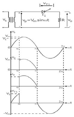
The load current i0 flows through 'R'
The waveforms for voltage & current are as shown above.
As load is resistive,
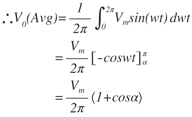
Output current is given as,
Hence shape of output current is same as output voltage
As T1 conducts only in positive half cycle as it is reversed bias in negative cycle, the ripple frequency of output voltage is-
fripple= 50 Hz (supply frequency)
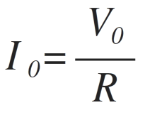
Average output voltage is given as,

i.e Area under one cycle.
Therefore T=2π&Vo(ωt) = Vmsinωt from α to π& for rest of the period Vo(ωt)=0
Power transferred to load,
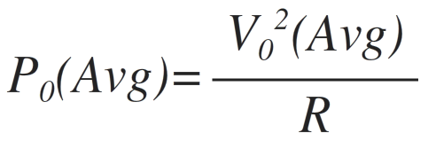
Thus, power & voltage can be controlled by firing angle.
Single Phase Half Wave Controlled Rectifier with 'RL' load:
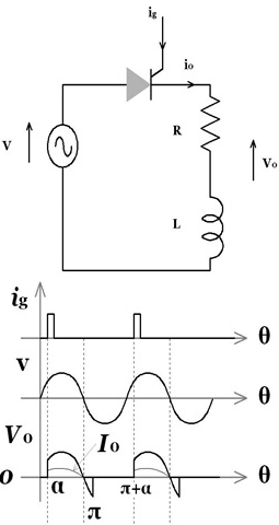
Figure above shows the single phase half wave rectifier with RL Load.
- Normally motors are inductive loads
L= armature of field coil inductance
R= Resistance of coil.
- In positive half cycle, SCR starts conduction at firing angle “α”.
- Drop across SCR is small & neglected so output voltage is equal to supply voltage.
- Due to 'RL' load, current through SCR increases slowly.
- At 'π', supply voltage is at zero where load current is at its max value.
- In positive half cycle, inductor stores energy & that generates the voltage.
- In negative half cycle, the voltage developed across inductor, forward biases SCR & maintains its conduction.
- Basically with the property of inductance it opposes change in current.
- Output current & supply current flows in same loop, so all the time io=is.
- After π the energy of inductor is given to mains & there is flow of 'io'. The energy reduces as if gets consumed by circuit so current also reduces.
- At 'β' energy stored in inductance is finished, hence 'io' becomes zero & 'T1' turns off.
- 'io' becomes zero from 'β' to '2π+α' hence it is discontinuous conduction.