Home > Analog CMOS Design > Signal Conditioning > Sampling Analog Signals
Sampling of Analog Signals :
Figure below shows the circuit to obtain the samples of an analog signal. The switch shown closes periodically under the control of clock. The closure time of the switch ‘t’ is relatively short and the samples obtained are stored on the capacitor. This circuit is known as Sample and Hold circuit. The S/H circuit consists of an analog switch that can be implemented by a MOSFET transmission gate, storage capacitor and a buffer amplifier. The sampled voltage levels are then fed to the input of A/D converter which provides an N bit binary number proportional to the value of signal sample.
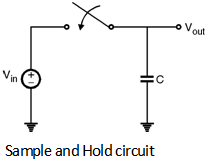
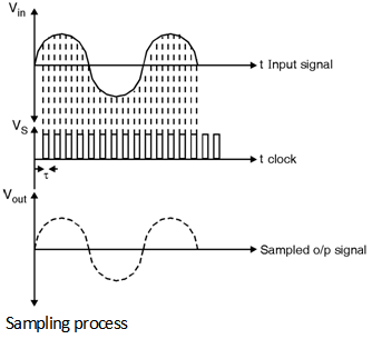
Figure below shows the input signal, clock and the sampled output signal of the S/H circuit shown in above Figure.