Home > mini projects > FREQUENCY SHIFT KEYING USING 555
Abstract -Frequency shift keying modulation technique is proposed here .Communication is integral part of human being. But as communication distance increases, the strength and power of the signal decreases. Hence ,in order to better long distance communication ,we are basically used modulation techniques. Frequency shift keying ,is one of the digital modulation technique
. it have better noise immunity .the modulation stage consists of ic 555 timer working in astable mode and generating frequency shift keying (FSK)signal.
I. I NTRODUCTION
As we know communication is the basic part of our life. Communication can be analog or digital. Now -a-days communication is mostly based on digital domain.In real, digital communication is very important aspect as it is mostly used in computers and many electronics communication.
For digital data transmission, there are different modulation techniques such amplitude shift keying, frequency shift keying and phase shift keying, to achieve a better signal at reception. Frequency-shift keying (FSK) is a method of transmitting digital signals. The two binary states, logic 0 (low) and 1 (high), are each represented by an different frequency of pulse. Logic 0 is represented by a wave at a specific frequency, and logic 1 is represented by a wave at a different frequency.
Basically, it is used in modem, point to point long distance communication. A modem a device which converts the binary data from a computer to FSK for transmission over telephone lines, cables, optical fiber, or wireless media. The modem also converts incoming FSK signals to digital low and high states (ie., logic 0 and logic 1), the language into which the computer can "understand". Today, a standard telephone modem operates at thousands of bits per second. Cable and wireless modems work at more than 1,000,000 bps (one megabit per second or 1 Mbps), and optical fiber modems function at many Mbps.
II. FSK MODUALTION
A frequency shift keyed transmitter has its frequency shifted by the message. There are different types of FSK corresponding to the number of frequencies transmitted. For example in QFSK we transmit four different frequencies which corresponds to the two data bits. Although there could be more than two frequencies involved in an FSK signal, in this experiment the message will be a binary bit stream, and so only two frequencies will be involved.
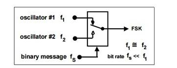
Figure1: FSK TRASMITTER
Its working is basically similar to a multiplexer. When logic 1 is to be transmitted it switches to one frequency(consider it to be f1) and when logic 0 is to transmitted it switches to some other frequency(consider it to be f2).In this experiment we are changing the frequency using 555 timer ic. Ic 555 is used in astable mode.
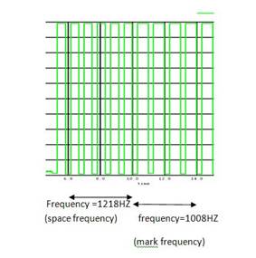
The frequency corresponds to logic'0' is called as space frequency and frequency corresponds to logic'1' is
called to mark frequency. Logic 1 frequency is low when compared to logic 0 frequncy. Just as given in figure below,
Figure2: INPUT AND OUTPUT WAVEFROMS The ic 555 pin description is given as following:
Input :
Output:
III. TIMER IC
IC 555 TIMER PIN DESCRIPTION
|
Pin |
description |
function |
|
1 |
Ground |
All voltages in |
|
circuit is measured |
||
|
with respect to this |
||
|
point |
||
|
2 |
Trigger input |
Output of the |
|
timer totally |
||
|
depends upon the |
||
|
amplitude of the |
||
|
external trigger |
||
|
voltage applied to |
||
|
this pin. |
||
|
3 |
Output |
The voltage is |
|
measured with |
||
|
respect to ground |
||
|
4 |
Reset |
Separate terminal |
|
is provided to reset |
||
|
flip flop externally |
||
|
5 |
control voltage |
By imposing a |
|
voltage to this the |
||
|
width of pulse can |
||
|
be changed |
||
|
6 |
Threshold voltage |
The timing (OUT |
|
high) interval ends |
||
|
when the voltage |
||
|
at THR (THR is |
||
|
greater than that at |
||
|
CTRL (2/3 VCC if |
||
|
CTRL is open). |
||
|
7 |
Discharge |
Open collector |
|
output |
||
|
8 |
vcc |
Supply voltage |
|
must be applied in |
||
|
between +5 to +18 |
||
|
volt |
The 555 timer IC is has many applications. It is mainly used in a variety of timers, pulse generation, and oscillator applications.Ic 555 is timer can be used as monostable, astable and bistable mode of operation.
Ic 555 is used in fsk generator. Basically, timer ic used in astable mode . An Astable Multivibrator is an oscillator circuit which continuously produces rectangular wave without using an external triggering. So Astable Multivibrator is also known as Free Running Multivibrator. In monostable and bistable type of multivibrator we need an external triggering Astable Multivibrator using 555 Timer is very simple circuit, it can be implemented easily, very stable and low cost. Due to these reasons 555 has a large number of applications and it is a popular IC.
Working of astable mode:
In astable multivibrator the output changes according to the charging and discharging of the capacitor (which is at trigger pin).
Initially,consider that flip flop is set
.therefore,Q'=0.this turns OFF the transistor Q1 and output of timer is high .since,Q1 is OFF ,capacitor C starts charging up towards +vcc though resistance Ra andRb .
Capacitor is connected to threshold terminal and reference voltage of comparator-1 is 2/3 vcc,when voltage is equal to or greater than 2/3 vcc,the output of comparator1 goes high.this turns on transistor Q1 and output of timer goes low.
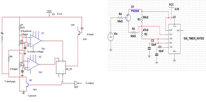
FIGURE 3: 555 TIMER IC IN ASTABLE MODE
Now,capacitor C discharges through transistor Q1 and resistor rb.when capacitor falls below 1/3 vcc ,which is reference
voltage of comparator 2 ,the output of comparator goes highand flip flop sets. hence Q'=0 .again transistor Q1 turns
OFF and output of timer is high. Again, process is repeated.
Capacitor charging time,tc=0.69(Ra+Rb)C
Capacitor discharging time,td=0.69RbC
Total time period of waveform=T=0.69(Ra+2*Rb)*c
Frequency ,f=1.45/(Ra+2*Rb)*C
It consists of a IC 555Timer which works in Astable Mode. Here ,transistor pnp act as a switch.The resistors R1 and R2and capacitor C determines the Frequency of the FSK modulated signal. The standard digital data input frequency is usually 150Hz. When the input is HIGH i.e. when the input binary data is of logic 1, the PNP transistor Q is off and IC 555 Timer works in the astable mode of operation. The frequency of the output FSK modulated signal is given by the Equation.
|
f= 1.45/(R1+2R2)C2 |
(1) |
The circuit diagram when the input is HIGH is shown in the Figure 5.
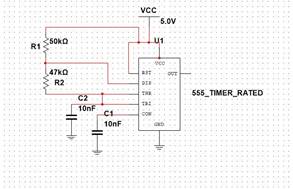
FIGURE 4: FSK MODULATION USING 555 TIME IC
IV. MODULATION
|
Modulation is the process of altering the |
|
|
Characteristics or changing the parameters of the carrier signal |
|
|
in accordance to the |
|
|
message signal. Here Frequency Shift Keying |
|
|
Modulated signal is obtained using IC 555 Timer.frequency |
|
|
shift keying is modulation in which it changes carrier |
|
frequency according to logic levels. The
circuit diagram for FSK Signal generation using IC
555 Timer is shown in Figure 4. Here the values of R1= 50K ohm, R2= 47K ohm
and C=10nF. When the input is LOW i.e. when the
input binary data is of logic 0, the PNP transistor Q is on and its connects the resistance R3 , across the resistance R1. Thus now the frequency of the output FSK modulated signal is given by the equation
|
f= 1.45/((R1||R3)+2R2)C2 |
(2) |
The circuit diagram when the
input is LOW is shown in the Figure 6.
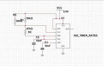
Here,
the value of R3=50K ohm. The capacitor C1 is used to
bypass noise and ripples from the supply. Mark frequency and space frequency are as shown in figure 7.
V. CALCULATIONS
R1=50KΩ
R2=47KΩ
R3=50KΩ
R4=10KΩ (input resistance)
C1=10nF
C2=10Nf
1)mark frequency
Frequency= f= 1.45/(R1+2R2)C2 =1.45/(50+2*47)*10*^(3)*10*10^(-9) =1008HZ
2)space frequency
Frequency= f= 1.45/(R1||R3+2R2)C2 =1.45/(50||50+2*47)*10*^(3)*10*10^(-9) =1218HZ
VI. WAVEFORMS
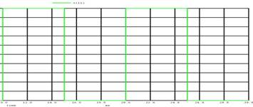
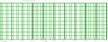
INPUT WAVEFORM
Frequency =100hz
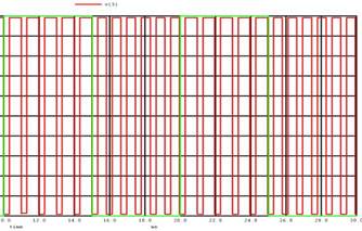
OUTPUT WAVEFORM
Space frequency=1218HZ
Mark frequency=1008HZ
Both plot of input and output waveform:
The major disadvantage is its high bandwidth requirement compared to ASK. Therefore FSK is extensively used in low speed modems having bit rates below 1200 bits/sec. The FSK is not preferred for the high speed modems because as we know ,with increase in speed, the bit rate also increases.This increases the channel bandwidth required to transmit the FSK signal. As the telephone lines have a very low bandwidth, it is not possible to satisfy the bandwidth requirement of FSK at higher speed. Therefore FSK is preferred only for the low speed modems.
VIII. CONCLUSION
Specification:
|
Sr.no. |
frequency |
value |
|
1. |
Mark frequency |
1008HZ |
|
2. |
Space frequency |
1218HZ |
VII. APPLICATIONS
It is used Point to point military communication and telephone modems. The technology is used for
communication systems such as amateur radio, caller ID and emergency broadcasts.
Thus ,in project frequency shift keying using ic 555 is achieved. It having two frequency such as mark frequency(1008HZ) and space frequency(1218HZ).frequency shift keying is better than amplitude shift keying as it have a better noise immunity.