In PFWR, for both the half cycles output is produced & in one direction only. The diagram below shows an inverting type of Precision FWR with positive output. It is also called as absolute value circuit because output signal swing is only in positive direction. So we get absolute value of input signal.
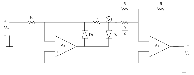
In positive half cycle of applied ac input signal, output of first op-amp (A1) is Negative. Therefore diode D2 is forward biased & diode D1 is reverse biased. Here op-amp A1 works as an inverting amplifier with gain =(-R/R)=-1
Therefore output of op-amp A1 is ,V=(-1) Vin=-Vin
Op-amp A2 works as an inverting adder. The two inputs to the op-amp A2 are voltage V (output of A1) and input voltage Vin. Thus output of op-amp A2i.e. Output voltage is given as
∴Vo=-[R/R Vin+R/(R⁄2) V ]
∴Vo=-[Vin+2V]
Substituting V=-V_in
∴Vo=Vin
In negative half cycle of applied ac input signal, output of first op-amp (A1) is positive. Therefore diode D2 is reversed biased & diode D1 is forward biased.
Due to virtual ground concept output of op-amp A1is zero. (∴V=0)
Thus output of op-amp A2, i.e. Output voltage is given as
∴Vo=-[R/R Vin+R/(R⁄2) V ]
∴Vo=-[R/R Vin+R/(R⁄2) (0) ]
But in negative half cycle input magnitude is negative therefore we get,
∴Vo=-[R/R (-Vin ) ]
∴Vo=Vin
Thus in both the half cycles output is positive & in one direction & also have same magnitude. Thus it is also called as non-saturating type of PFWR because op-amp A1 is not going in saturation.
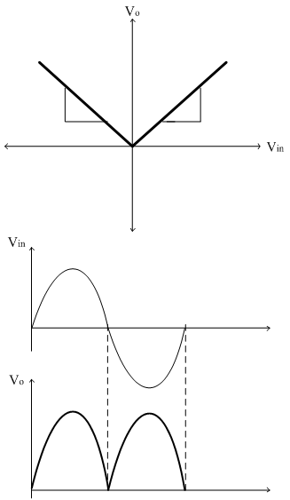
The transfer characteristics and input-output waveforms of PFWR are shown below,