Home > finite state machines > Metastability > Metastability measurement setup
Metastability measurement setup:
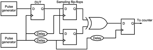
Figure shows a test circuit to measure metastable parameters of a synchronizer.
In this case, we use two different pulse generators to provide a data rate of 1 MHz and a clock rate of 2 MHz. The data transitions are randomly and evenly distributed over the entire clock period of about one transition per clock cycle. The data transitions are also evenly distributed within the failure time window tW. At the output of the DUT, there are two well characterized sampling flip-flops. These two flip-flops uses the same clock signal used by the DUT. The first sampling clock is delayed by td. Since the probability decreases exponentially with time, the condition easily satisfied. To run the test, tCO is used as a base delay with tW = 0. Here, different MTBF with increasing tM until MTBF is greater than 60 sec is taken. When the MTBF results are plotted on semilog paper, they gives rise to a best-fit straight line with slope - 1/k2. k1 and is calculated by inserting a k2 value into the MTBF equation. Further, with k1 and k2, we can can easily find tCOM for a chosen MTBF, fCLK and fDATA