Home > Analog CMOS Design > CMOS Opamp > Cascode Op amp
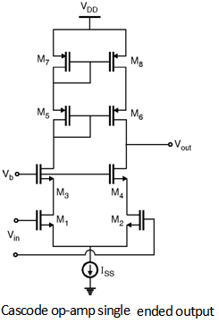
In order to achieve high gain, the differential cascode topology can be used. Figure below shows the single ended output configuration of cascode opamp.
Further, Figure below shows the differential output configurations of cascode opamp topology respectively.
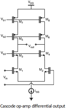
These configurations are also called as the telescopic cascode op-amps. The voltage gain of these circuits can be given as,
An = – gm1, 2 [(gm3, 4 × ro1, 2 × ro3, 4) || (gm5, 6 × ro5, 6 × ro7, 8)]
* The drawback to telescopic topology is that the output swings are relatively limited.
The output swing is given by,
Swing = 2 [VDD - (VOD1 + VOD3 + V CSS + | VOD5 | + | VOD7 |)]
other drawback of telescopic cascode is the difficulty in shorting their inputs and outputs