Home > mini projects > Zener Diode Tester
Abstract -The main purpose of this report is to obtain a Zener diode tester using 555 timer. A 555 timer, which works in astable mode, is used to generate a pulse and then given to a transistor driven circuit to test the Zener diode. The voltage across the Zener diode under test is calculated.
I Introduction
Zener diode: A Zener Diode is a reverse biased, heavily doped semiconductor P-N junction diode which is operated in breakdown region. Different semiconductors can be used to obtain a diode(like Silicon, Germanium etc.,).
When a zener is forward biased, its characteristics are just as those of an ordinary diode. As the reverse voltage applied to P-N junction is increased, a value is reached at which the current increases greatly from its normal cut off value. This voltage is called a Zener voltage Vz or breakdown voltage. So, when a Zener diode is reverse biased it has sharp breakdown voltage called Zener voltage Vz.
Below knee(point at which current changes drastically),the breakdown voltage Vz remains practically constant. This ability of diode is called as regulating ability. This is an important feature which is used to maintain a constant voltage across its terminal over a specified range of Zener current values. Thus Zener diode is used for voltage regulation.
555 timer : The 555 integrated circuit timer can be applied to myriad of timing applications like monostable multivibrators, astable multivibrators, ramp generators, sequential timers etc., The internal circuit of 555 timer has two comparators, one RS flipflop, three 5k resistances in potential divider configuration, two transistors(npn and pnp) and an inverter.
Following are the pins of 555 timer ic:-
GND: low level(0 V)
TRIG: This pin is connected to inverting terminal of second comparator.O/p of comparator goes high when this i/p is less than 1/3Vcc.
OUT:Output pin
RESET:A timing interval may be reset by driving this input to GND.
CONTROL VOLTAGE:Provides "control" access to the internal voltage divider .
THR: This pin is connected tonon inverting terminal of second comparator.O/p of comparator goes low when this i/p is less than 2/3Vcc.
DIS: Capacitor discharges through this pin
- VCC: Supply voltage
Astable mode: In astable mode, the 555 timer puts out a continuous stream of rectangular pulses having a specified frequency
II Design
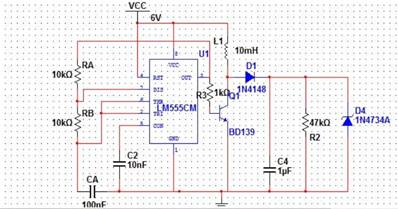
To obtain a Zener diode tester, connections are made as shown in figure.The output of 555 timer is connected to the base of a transistor through a resistance 2k.An inductor is connected to the collector of the transistor,from Vcc.The transistor is in common-emitter configuration. A diode is connected from the collector to a capacitor and resistor as shown. Zener diode to be tested is connected across the resistor 47k.ic555 timer is connected such that it works in astable mode.
III Analysis
Working of 555 timer in astable mode, Working of an astable multivibrator:
When initially power is turned ON, Trigger Pin voltage is below Vcc/3, that makes the lower comparator output HIGH and SETS the flip flop and output of the 555timer is HIGH.
This makes the transistor Q1 OFF, because Qbar, Q'=0 is directly applied to base of transistor. As the transistor is OFF, capacitor C1 starts charging and when it gets charged to a voltage above than Vcc/3, then Lower comparator output becomes LOW (Upper comparator is also at LOW) and Flip flop output remains the same as previous (555 output remains HIGH).
Now when capacitor charging gets to voltage above t 2/3Vcc,the voltage of non-inverting terminal (Threshold PIN 6) becomes higher than the inverting terminal of the comparator. This makes Upper comparator output HIGH and RESETs the Flip flop, output of 555timer becomes LOW.
As soon as the output of 555 gets LOW, means Q'=1, then transistor Q1 gets ON and shorts the capacitor C1 to the Ground. So the capacitor C1 starts discharging to the ground through the Discharge PIN 7 and resistor R2.
As capacitor voltage goes below the 2/3 Vcc, upper comparator output becomes LOW, now SR Flip flop remains in the previous state as both the comparators are LOW.
While discharging, when capacitor voltage goes below Vcc/3, this makes the Lower comparator output HIGH (upper comparator remain LOW) and Sets the flip flop again and 555timer output becomes HIGH.Transistor Q1 is OFF and again capacitor C1 starts charging
Charging time
t1=0.693CA(RA+RB)
Discharging time:
t2=0.693RBCA
Working of the tester circuit:
555 timer works in astable mode.
When the o/p of 555 timer is low for the first time, capacitor gets charged up.
When the o/p goes high, the transistor is on and current flows through the transistor due to Vcc. Inductor develops magnetic flux. Diode is reverse biased thus no current flows through diode. During this time, capacitor discharges through the resistance maintaining the voltage across zener diode constant.
When the o/p goes low again, transistor is off and the current direction changes suddenly to the opposite direction, forward biasing the diode. This is opposed by the inductor. Thus current flows through the diode charging up the capacitor and also keeping voltage constant across zener diode.
This process is repeated and the voltage across Zener diode remains constant. Thus voltage is regulated across Zener diode. If the Zener diode is working properly, voltage across it remains constant. If the Zener diode is faulty, current does not flow through it and voltage across it is not equal to its regulated voltage but, Vcc with some drop.
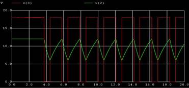
O/P of astablemultivibrator is :
Calculation of charging and discharging time:
RA=RB=10k
CA=100n
A.Charging time
t1=0.693CA(RA+RB)
=0.693x100n(10k+10k)
=1.386x10⁻³
B.Discharging time:
t2=0.693RBCA
=0.693x10kx100n
=6.93x10⁻⁴
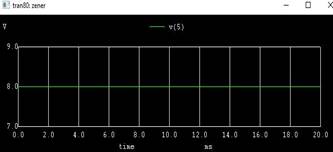
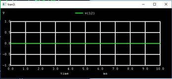
O/P of a Zener diode working properly is:
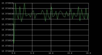
O/P of a faulty diode is:
O/P of normal diode
V.Conclusion
In this report, Zener diode tester has been obtained using a 555 timer, As this circuit uses regulated supply through 555 timer, it does not damage zener diode under test.555 timer can be used to check different Zener diodes, not just one ,by changing Vcc.Applications of Zener diode include, Voltage Regulation, Meter protection, Peak clipper, Switching operation.