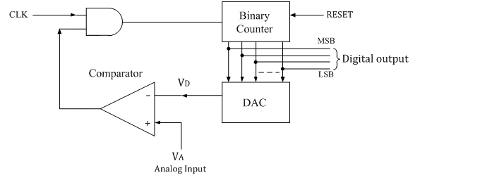
The counter type ADC is constructed using a binary counter, DAC and a comparator. The output voltage of a DAC is VD which is equivalent to corresponding digital input to DAC.
The following figure shows the n-bit counter type ADC.
Operation:
The n-bit binary counter is initially set to 0 by using reset command. Therefore the digital output is zero and the equivalent voltage VD is also 0V.
When the reset command is removed, the clock pulses are allowed to go through AND gate and are counted by the binary counter.
The D to A converter (DAC) converts the digital output to an analog voltage and applied as the inverting input to the comparator. The output of the comparator enables the AND gate to pass the clock.
The number of clock pulses increases with time and the analog input voltage VD is a rising staircase waveform as shown in figure below.
The counting will continue until the DAC output VD, equals and just rises more than unknown analog input voltage VA. Then the comparator output becomes low and this disables the AND gate from passing the clock.
The counting stops at the instance VA< VD, and at that instant the counter stops its progress and the conversion is said to be complete.
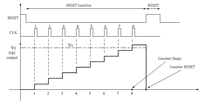
The numbers stored in the n-bit counter is the equivalent n-bit digital data for the given analog input voltage.
Advantages:
1 Simple construction.
2 Easy to design and less expensive.
3 Speed can be adjusted by adjusting the clock frequency.
4 Faster than dual slope type ADC.