Home > mini projects > Asynchronous Device for Serial Data Transmission and Reception for android data transmission
|
Asynchronous Device for Serial Data Transmission and Reception for android data transmission) |
I NTRODUCTION
The Internet of Things (IoT) is the network of physical devices, vehicles, home appliances and other items embedded with electronics, software, sensors, actuators, and connectivity which enables these objects to connect and exchange data.Each thing is uniquely identifiable through its embedded computing system but is able to inter-operate within the existing Internet infrastructure.The IoT allows objects to be sensed or controlled remotely across existing network infrastructure, [7] creating opportunities for more direct integration of the physical world into computer-based systems, and resulting in improved efficiency, accuracy and economic benefit in addition to reduced human intervention.When IoT is augmented with sensors and actuators, the technology becomes an instance of the more general class of cyber-physical systems, which also encompasses technologies such as smart grids, virtual power plants, smart homes, intelligent transportation and smart cities."Things", in the IoT sense, can refer to a wide variety of devices such as heart monitoring implants, biochip transponders on farm animals, cameras streaming live feeds of wild animals in coastal waters, automobiles with built-in sensors, DNA analysis devices for environmental/food/pathogen monitoring,or field operation devices that assist firefighters in search and rescue operations.Legal scholars suggest regarding "things" as an "inextricable mixture of hardware, software, data and service".
As this usage of IOT devices are increasing day by day it is an essential need to build a device which could do the work of android debug bridge for variety of devices. It's not possible to integerate the android debug bridge in each devices because some devices might have low performance. So to get over this problem this Asynchronous Device comes into existence.
Android Debug Bridge (adb) is a versatile command-line tool that lets you communicate with a device. The adb command facilitates a variety of device actions, such as installing and debugging apps, and it provides access to a Unix shell that you can use to run a variety of commands on a device. It is a client-server program that includes three components:
A client , which sends commands. The client runs on your development machine. You can invoke a client from a command-line terminal by issuing an adb command.
A daemon (adbd) , which runs commands on a device. The daemon runs as a background process on each device.
A server , which manages communication between the client and the daemon. The server runs as a background process on your development machine.
This bridge is inplemented as a hardware device which has the same function.
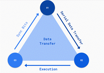
Following is the block diagram for this device.
BLOCK DIAGRAM
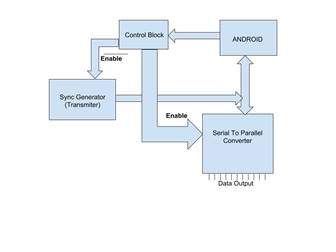
A. Serial to Parallel Converter
In telecommunication and data transmission, serial communication is the process of sending data one bit at a time, sequentially, over a communication channel or computer bus. This is in contrast to parallel communication, where several bits are sent as a whole, on a link with several parallel channels.Serial communication is one of the simplest ways of communication between a microcontroller and PC or vice versa. It requires only single wire for transmission of a data and another for receiving.This communication can be used for controlling the robot from a PC manually or the computer program controls it.In telecommunication and data transmission, serial communication is the process of sending data one bit at a time, sequentially, over a communication channel or computer bus. This is in contrast to parallel communication, where several bits are sent as a whole, on a link with several parallel channels.
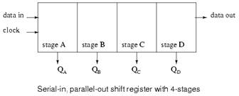
The practical application of the serial-in/parallel-out shift register is to convert data from serial format on a single wire to parallel format on multiple wires. Perhaps, we will illuminate four LEDs (Light Emitting Diodes) with the four outputs ( QA QB QC QD ).
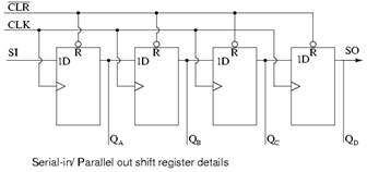
The above details of the serial-in/parallel-out shift register are fairly simple. It looks like a serial-in/ serial-out shift register with taps added to each stage output. Serial data shifts in at SI (Serial Input). After a number of clocks equal to the number of stages, the first data bit in appears at SO (QD) in the above figure. In general, there is no SO pin. The last stage (QD above) serves as SO and is cascaded to the next package if it exists.
If a serial-in/parallel-out shift register is so similar to a serial-in/ serial-out shift register, why do manufacturers bother to offer both types? Why not just offer the serial-in/parallel-out shift register? They actually only offer the serial-in/parallel-out shift register, as long as it has no more than 8-bits. Note that serial-in/ serial-out shift registers come in bigger than 8-bit lengths of 18 to to 64-bits. It is not practical to offer a 64-bit serial-in/parallel-out shift register requiring that many output pins. See waveforms below for above shift register.
B. Sync Generator
A sync pulse generator is a special type of generator which produces synchronization signals, with a high level of stability and accuracy. These devices are used to provide a master timing source for a video facility. The output of an SPG will typically be in one of several forms, depending on the needs of the facility:
A continuous wavesignal
In standard-definition applications, a bi-level sync signal, often with a colorburst signal in facilities that have analog equipment.. As the resulting signal is usually indistinguishable.In some high-definition applications, a 'tri-level sync' signal is used instead.
C. Control Block
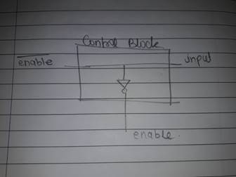
In this block we have one output going through not gate and one simply passing the input signal. As the serial to parallel conversion is done input signal goes high and disable the conversion block and enables the Sync generator block. This is how we can switch between reading and writing modes.
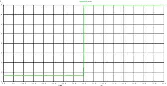
OUTPUT WAVEFORMS
I. Pseudo Random Sync Generator output
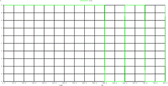
II. Serial to Parallel line 4
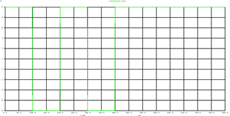
III. Serial to Parallel line 5
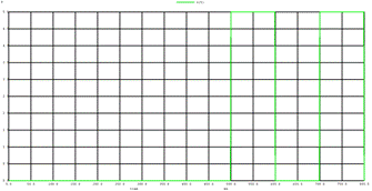
IV. Serial to Parallel line 6
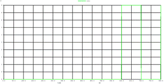
V. Control block output and input to serial to parallel
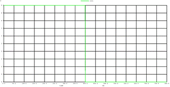
VI. Control block output and input to pseudo random sync Also sync from USB
CONCLUSION
The device is simmulated in NGSPICE and ouptut is observed as above.