Figure below shows the Circuit Diagram and Waveform of step up chopper.
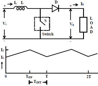
• Step-up chopper is used to obtain a load voltage higher than the input voltage V.
• The values of L and C are chosen depending upon the requirement of output voltage and current.
• When the chopper is ON, the inductor L is connected across the supply. The inductor current ‘I’ rises and the inductor stores energy during the ON time of the chopper, tON.
• When the chopper is off, the inductor current I is forced to flow through the diode D and load for a period, tOFF.
• The current tends to decrease resulting in reversing the polarity of induced EMF in L. Therefore voltage across load is given by,

Hence, V0 > V.