Rectifier circuit gives average value of input signal; but in practice we need peak value of input signal. This is achieved by peak detector circuit. The following figure shows a simple peak detector circuit using diode and capacitor.
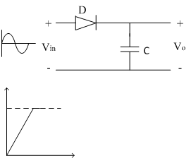
In the positive half cycle, diode D is forward biased and capacitor C starts charging. When input reaches its peak value capacitor gets charged to positive peak value.
In negative half cycle, as input decreases, diode D is reversed biased and capacitor is isolated and holds the peak value of previous cycle. Hence called as peak detector.
But in practice, output is taken across some load RL, so when input voltage decreases capacitor discharges through load RL. To avoid this select RL of very large value so that capacitor discharges very slowly hence almost holds the charge. Whatever charge it lost through RL is gets back in next half cycle.
Limitation:
The diode D is acting as an instant switch, so supply gets loaded.
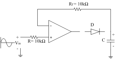
To avoid the loading while charging capacitor, we use op-amp as follows. Op-amp is placed between input and diode D so loading is avoided as shown in circuit diagram below,

In positive half cycle, output of op-amp is positive so diode D is forward biased, capacitor charges to peak value of input signal.
In negative half cycle, when input decreases diode D is reversed biased and capacitor is isolated and holds the charge of previous half cycle. Since diode is reversed biased, op-amp is in open loop condition and goes into saturation. Capacitor starts discharging through RL.
Let peak value of input is Vin peak = 10 V.
In the positive half cycle the capacitor holds the positive peak value i.e. +10V. In the negative half cycle negative peak input is Vinpeak = -10V. Due to negative output diode D is reverse biased and acts as open circuit isolating op-amp output and capacitor C. Capacitor C has a charge of +10V from previous positive half cycle. This voltage is appeared to be as input to inverting terminal of op-amp.
Therefore differential input (Vid) to op-amp is,
Vid=-10-10=-20V=2×V(in peak)
For every op-amp there is a limit for maximum differential input voltage Vid. So care must be taken while selecting op-amp.
The load resistance RL is not possible to have a very large value always, so we use another op-amp as follows,

Here second op-amp acts as a voltage follower. Its input impedance is very high so capacitor discharges very slowly i.e. capacitor almost holding the charge. Therefore output voltage is nothing but voltage across capacitor (Peak value of input signal).
Vout = Voltage across capacitor, Vc
As output impedance of voltage follower is very small we can connect any value of RL.