Home > combinational logic circuits > half subtractor
Half-Subtractor
Subtraction is carried out column wise in the same way as that of the decimal number system.
In the first step, we subtract the LSBs and then move ahead towards the MSB. Wherever the
subtrahend (the bit to be subtracted) is larger than the minuend, we borrow from the next adjacent higher bit position having a '1'.
Below is the example, In this example the different steps of subtracting (1001) from (1100). Here, 1 is borrowed from the second MSB position, leaving a 0 in that position. The borrow is first brought to the third MSB position to make it 10. Out of 10 in this position, 1 is taken to the LSB position to make 10 there, leaving a 1 in the third MSB position.
10−1 in the LSB column gives 1, 1−0 in the third MSB column gives 1, 0−0 in the second
MSB column gives 0 and 1−1 in the MSB also gives 0 to complete subtraction. The Subtraction
of mixed numbers is also done in the same manner. The binary subtraction steps are given in below figure.
In digital arithmetic circuits the one way to carry out the subtraction of two binary numbers is the addition of 2's complement of the subtrahend to the minuend. This clearly shows that the subtraction operation can be carried out by using the adder circuits. In this section we will see the other counterparts of the half-adder and the full adder circuits for the half-subtractor and full subtractor implementation.
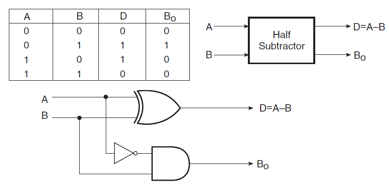
A half-subtractor is mainly used to subtract one binary digit from another to produce a DIFFERENCE output and a BORROW output. The BORROW output here specifies whether a '1' has been borrowed to perform the subtraction. Figure below shows the block diagram of half subtractor.
Half-subtractor is used to subtract one binary digit from another to give DIFFERENCE output and a BORROW output. The truth table of a half-subtractor is shown in figure below.
1) When the inputs minuend (A) =0, Subtrahend (B) =0 then the difference (D) = 0 and Borrow out (Bo) =0
2) When the inputs minuend (A) =0, Subtrahend (B) =1 then the difference (D) = 1 and Borrow out (Bo) =1
3) When the inputs minuend (A) =1, Subtrahend (B) =0 then the difference (D) = 1 and Borrow out (Bo) =0
4) When the inputs minuend (A) =1, Subtrahend (B) =1 then the difference (D) = 0 and Borrow out (Bo) =0
The Karnaugh maps for the for DIFFERENCE output D is shown in figure as it is clear from the Karnaugh maps, no simplification is possible for the difference output D. The expression for difference (D) is also shown in figure. Here, the DIFFERENCE output is an EX-OR gate.
The Karnaugh maps for BORROW output Bo is shown in figure below. As it is clear from the two Karnaugh maps, simplification is possible for the BORROW output Bo. The simplified expression for Bo is also shown in figure. Here, the BORROW i.e. Bo is AND gate with complemented input A.
Figure below shows the logic implementation of a half-subtractor. Comparing a half-subtractor with a half-adder, it can be seen that, the expressions for SUM and DIFFERENCE outputs are same. The expression for BORROW in the case of the half-subtractor is more or less same with CARRY of the half-adder. However, the case of BORROW output the minuend is complemented and then ANDing is done.
Points to remember and Summary