Home > mini projects > PIR MOTION SENSOR
PIR MOTION SENSOR
ABSTRACT
This project contains the model of a PIR motion sensor which is used at places where
a moving living object detection is required. It allows us to detect the presence of a
people, animals when they are located in the range of the sensor. It is less complex,
feasible to purchase, is a low power device and reliable i.e. it does not wear out soon
and hence it is used in many gadgets and appliances. It is abbreviated as a "Pyroelectric or Passive Infrared Sensor". These are widely used in smart systems where a system has to respond automatically in the presence of a person such as in staircases, rooms, street lights,
etc and turns them off in their absence due to which there is reduction in the consumption of energy and also a person need not mechanically perform the task thus reducing the monotonous work.
1.INTRODUCTION
A motion detector is a device that detects moving objects especially people. It is often integrated as a component of a smart system to receive alerts. It contains a Pyroelectric sensor which is an optical sensor that senses the moving object through emission or reflection of infrared rays. It is sensitive to a person's skin temperature through emitted black body radiation at mid-infrared wavelengths, in contrast to background objects at room temperature.
PIR Sensors have a 3 pin circuit, one is the ground pin, other is the supply voltage pin generally 5V and the third pin is the output signal pin. The PIR sensor board results in a digital output which we recognize as a pin having a flip from low to high or high to low. It is difficult to differentiate between different energy emitting bodies like humans, animals, moving objects, heat emitting bodies, etc. Thus a potentiometer is generally used to tune the frequency of the input system to that of the emitting source to be selective. Once the moving body is out of the range of the detection of the sensor, it results in a low signal indicating the absence and thus system goes to a stand by state waiting for an input radiation.
2.CONSTRUCTION
The PIR sensor consists of a pyroelectric element which generates a signal when exposed to heat or temperature variation.
It contains a special lens called Fresnel lens which sets the range and sensitivity of the sensor. It helps in converging the detected infrared signals to the pyroelectric element. To make the signal usable by the appliances, it has to be amplified to a dc level of atleast 5v which is done using a 2 stage amplifier and a comparator circuit. See figure 1.
The amplifier and comparator circuit was designed to get low power output to avoid high power dissipation.
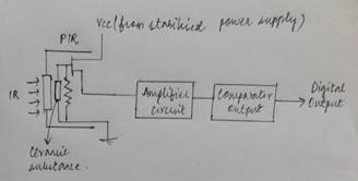
Figure 1: A generalised PIR sensor design
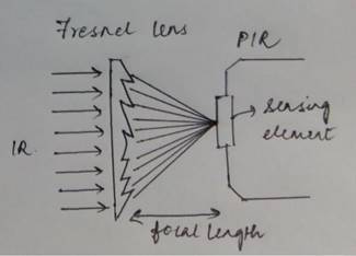
The Fresnel lens condenses light, providing a larger range of IR to the sensor. To increase the range of action of the PIR sensor, the lens is split into multiple sections each section of which is a fresnel lens.
The lens can change the breadth, range, sensing pattern, very easily.
low power devices, we have constructed delay circuits using flip flops of CMOS technology.
3.WORKING OF A PIR SENSOR
Any object be it living or non-living emits radiations due to its heat. In case of humans or animals, IR radiations are emitted because of body heat.
The Fresnel lens captures these rays and focuses them onto the pyroelectric element as shown in figure 3.
The infrared rays from the person are focused at the sensing element and thus detected.
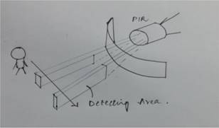
Figure 2: Fresnel lens
As the signal amplified is available as a trigger only for a short period which is not sufficient to drive any circuits, a delay circuit was constructed which helps in rectifying the same. The delay circuits can be constructed using a duty cycle controller, flip-flops, etc. As the CMOS devices are
The sensing element thus produces a analog output signal on detection of a heat source movement. This signal is full wave rectified to get a pulse. This pulse is of very few volts and thus has to be amplified so that it can be used elsewhere. Hence a two stage amplifier followed by a comparator is used to get appropriate voltage level.
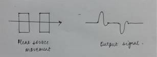
Figure 4: Output analog signal
 The output analog waveform on full wave rectification gives a pulse
which is given to an amplifier and a comparator to get a digital output
with immunity to noise. This digital sensor output is on only for a
certain amount of time, and re triggering is required to get consistent
output. And thus a delay circuit is built using flip-flops.
The output analog waveform on full wave rectification gives a pulse
which is given to an amplifier and a comparator to get a digital output
with immunity to noise. This digital sensor output is on only for a
certain amount of time, and re triggering is required to get consistent
output. And thus a delay circuit is built using flip-flops.
Figure 5:Full wave rectifier
4.FEATURES OF A PIR SENSOR
1. Motion Detection.
2. Low Noise.
3. Supply Voltage - 5V.
4. Delay Time Adjustable.
5. Standard Pulse Output.
5.DISADVANTAGES
1)Limited range
2) poor line of sight
3) PIR sensor pot should be adjusted in such a way to detect the humans only.
6.APPLICATIONS
1)Street lights
2)Security system
3)Automatic door opening
4)Any power saver circuits
The applications of the PIR sensor are based on the requirement of the system, such that the energy is not wasted and the system is automated without human intervention. The system is thus designed with low power, cost reliability and exhibits more immunity to noise.
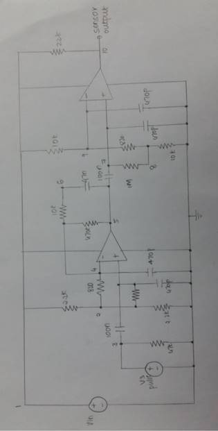
Figure 6: Amplifier and comparator circuit
7.RESULTS
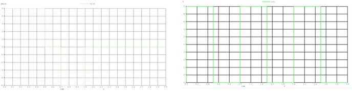
Figure 7: Output of PIR sensor
Figure 8: Output of full wave rectifier
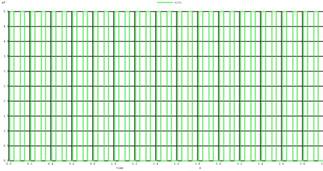
Figure 9:Input to amplifier 5mV(output of full wave rectifier)
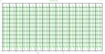
Figure 10: Output of amplifer 5V
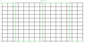
Figure 12: Output of the delay circuit
8.DISCUSSIONS
A practical PIR system has less immunity to noise and thus we have designed a step wise amplification system with reduction of noise. This circuit is such that only the actual signal is amplified in contrast to the high frequency noise.
The amount of time the trigger of the sensor remains on is less and thus a delay circuit was added such that its working is observed for certain amount of time.
As we have used CMOS technology for desired delay circuit,that reduces the power dissipation effectively.This is further a high speed device as the propagation delay is less.