Home > mini projects > Short Circuit Protected Power Supply
Short Circuit Protected Power Supply
Abstract -Short circuit protection is very important for the work concerned in any field, as there are many chances for small or heavy damage to occur, if protection is not provided. The main object is to design a short circuit protected power supply which also has ability to provide voltage regulation with help of bipolar junction transistors, resistors and capacitors a series resistance. Its function is to supply a stable voltage, to a circuit or device that must be operated within certain power supply limits. It is widely used as the voltage requirements are easily available in households.
1. INTRODUCTION
Electronic circuits consist of many small and fragile components which are very sensitive to any kind of change in current or voltage. Unstable power supplies will rise a big risk for the circuit.
Another problem which occurs is due to the size of PCB boards, and the size of the electrical components, there is an increased possibility of a short circuit occuring. Damage to these components leads to the need of replacing the entire component which tends to increase the cost of the circuit which is undesirable.
Hence the need arises for a regulated power supply, as protection of the power supply is very important as it ensures the circuit works correctly and that no damage will arise either.
There are many types of regulated power supply circumstances available, ranging from transformers used for the input, to a full wave bridge rectifier, both having a alternating current supply. The regulating components range from integrated chips or transistors with
Uses of Regulated Power Supply:
Various places it practically used:
â— Mobile phone power adaptors
â— Various household appliances
â— A number of amplifiers and oscillators require regulated power supply
2. Components:
There are four important parts to the short
circuit protected power supply. They are:
â— Rectification
â— Filtration
â— Regulation
â— Load
3. Block Diagram of Circuit:
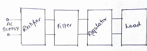
1.Rectification :
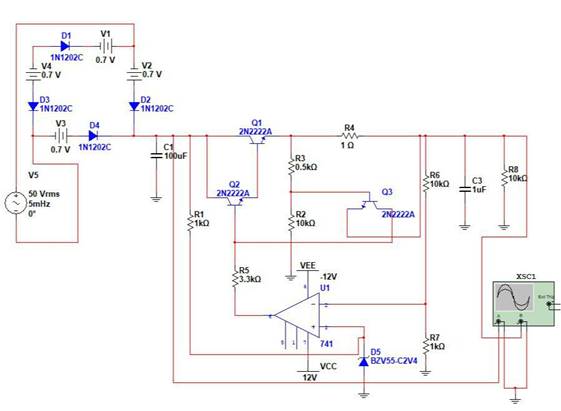
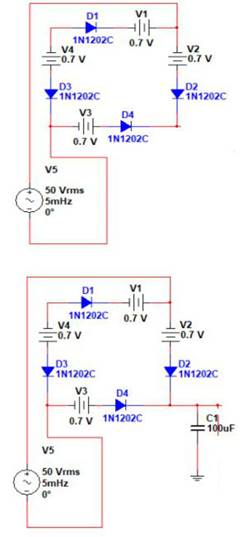
This circuit consists of a full wave bridge rectifier which converts the unstable alternating current into a constant unidirectional pulsatingdirect current which is within certain limits specified by the circuit. A bridge circuit is made up of four PN junction diodes, as shown below. During the positive half cycle of AC, the diodes D2 and D3 are reverse biased. When the diodes are reverse biased, due to the voltage drop, the diodes act as an open switch. Thus current will not flow between these two diodes. The opposite diodes D4 and D1 will be forward biases which thus acts as closed switches and allow current to flow. Due to this the output waveform, will be a rectified signal.
2. Filtration:
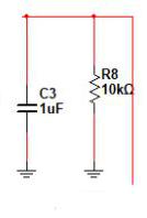
The rectified pulsatingdirect current has constant value but may contain ripples. This is undesirable, so to remove this we use a capacitive filter as the load. The filter is connected to the rectifier output. With the increase in voltage, the capacitor charges till the maximum value is reached.
When the instantaneous value decreases and the capacitor discharge begins. There is an exponential decrease which passes through the capacitive filter and a ripple free DC value is obtained.
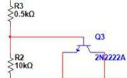
3. Regulation:
This is the fourth and final part of the regulated power supply. The filtered output is passed through a regulator to ensure no change is observed in the output in case of any change in power supply or other factors such as temperature variations. The regulated output is then sent to the load where there will be no worry about voltage spikes thus no damage to the components. In this circuit we use a zener
During the negative half cycle, the biases of the four diodes changes and current then flows through D2 and D3. A similar waveform is observed during this half cycle.
controlled transistor series voltage regulator, or also known as the emitter follower voltage regulator. The transistor used is series pass transistor.
4. Load:
The output voltage that is obtained from the series pass transistor is fed into the load, which consists of a resistance and a operational amplifier. A capacitor is connected in parallel with the load, so as to avoid any possible oscillations. To ensure that there will be no damage to the transistor is case of a short, another parallel resistor and transistor is connected to the ladder transistor.