ASM is an algorithm consists of a few steps, which is used to simplify a sequential digital system. An ASM chart is resembles a conventional flow chart but the difference is, a conventional flow chart does not have timing relationships but the ASM takes timing relationship into account. An ASM chart describes the sequence of events as well as the timing relationship between the states of a sequential controller and the events that occur while going from one state to the other. It is employed to design a sequential circuit having a large number of external inputs because with a large number of external inputs it becomes very difficult to use state tables for designing the circuit. ASM Chart Notations : The different blocks used in the ASM chart are :
- The state box
- The decision box
- The conditional box
State Box :
The state box is used to indicate the control sequence in the state. The general description and typical example of state box is as shown in Figure below.
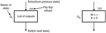
State box description :
- A state box is a rectangular in shape.
- The circuit outputs that can occur whenever the circuit is in the corresponding state regardless of input values are listed inside the box.
- On the right hand top corner of the box the list of flip flop values which represents state are written.
- The name of the state for example, Qi, Si, etc. can be written at the left corner of the rectangular box.
- The input to the state box is indicated by “Entry†and output to next state is denoted by “Exitâ€.
Decision Box :
The decision box defines the decision based on certain condition which shows the effect of an input on the control system. The general description and typical example of decision box is as shown in Figure below.
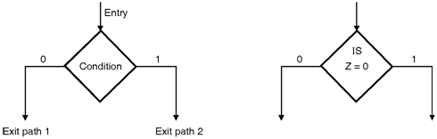
Decision box description :
- A decision box is a diamond shape box.
- The decision box has one entry and two exit paths depends upon the whether the input condition is true or false.
- The input condition to be tested is written inside the diamond box.
- Each value either true or false depend upon an expression inside the diamond box leads with exit paths from that box.
- These paths are connected to the blocks corresponding to the next states of the circuit.
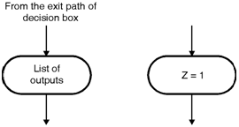
Conditional box description :
- A conditional box is a oval shape box.
- The difference between state box and conditional box is only the rounded corner.
- The input path for the conditional box always comes from one of the exit paths of a decision box.
- The outputs produced are listed inside the conditional box are generated during a given state.