The following figure shows the inverting configuration of comparator. The input signal is applied at inverting terminal of op-amp. The reference voltage Vref = 0V.
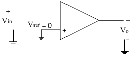
Due to open loop configuration of op-amp, the output goes into saturation.
The operation of the comparator is explained with the following two equations
1. If Vin>Vref then Vo= – Vsat
Thus for the positive half cycle of the input signal the above condition is true. So for the positive half cycle of input signal, the output goes into negative saturation i.e. –Vsat. The input and output waveforms are shown below.
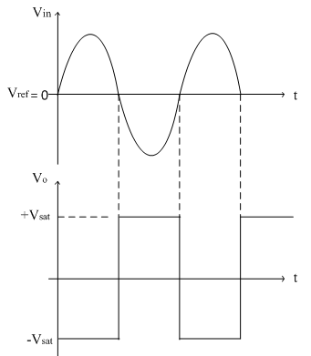
2. If Vin<Vref then Vo= +V_sat
Thus for the negative half cycle of the input signal the above condition is true. So for the negative half cycle of input signal, the output goes into positive saturation i.e. +Vsat.
The transfer characteristics are shown in figure below.
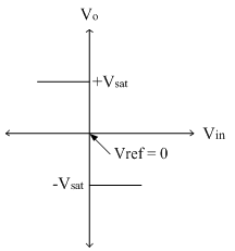
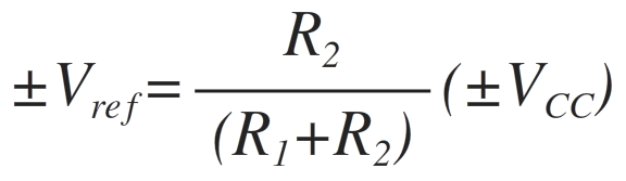
The reference voltage is zero here and hence the circuit is also called as inverting zero crossing detector. The reference voltage can be changed externally with the help of potential divider arrangement. This reference voltage can be either positive or negative as shown in circuit diagram below.
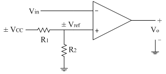
If the supply voltage is positive, the reference voltage is also positive. If the supply voltage is negative, the reference voltage is also negative.
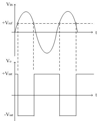
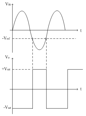
The following figure shows the input and output waveforms for positive reference and negative reference.
The transfer characteristics of both positive as well as negative reference are shown below.
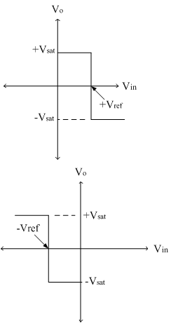
The transfer characteristics are basically a graph of output voltage versus input voltage. From the above characteristics, it is observed that the reference voltage (or reference point) is the point at which the state change occurs i.e. the transition from one state to other state. In other words, the circuit is triggered at the reference point hence it is also called as triggering point. The reference voltage can be changed externally and also can be either positive or negative as discussed above. Thus the reference point can have a trip on input axis anywhere, and hence it is also referred as trip point or trip voltage. Also at the reference point the state change occurs at the output when input signal crosses the reference voltage. Thus reference voltage is also called as threshold voltage at which the comparator is changing its output state.