Home > Analog CMOS Design > MOSFET Fundamentals > C V Characteristics
C-V Characteristics :
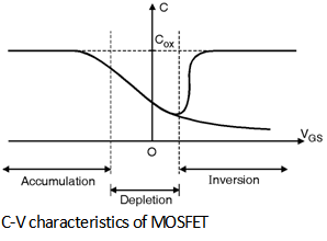
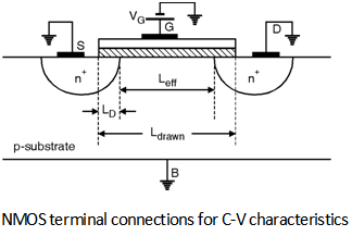
Consider the terminal connections of n-channel MOSFET shown in Figure below. Which consists of VS = 0, VD = 0 and V B = 0 and a bias is applied to the gate terminal. Depending upon the gate bias there are different regions of operation in C-V curve that are accumulation, depletion and strong inversion. We will discuss each region of operation in details in this section.
In this region of operation the gate to source bias is negative because of this the holes from the substrate are attracted under the gate region as shown in Figure below.
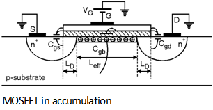
There are three types of capacitances are involved that are capacitance between gate electrode and substrate (Cgb), capacitance between gate and drain terminals (Cgd) and capacitance between gate and source terminals (Cgs).
If tox is the oxide thickness the Cgb is given as :
Cgb = =
Where ÃŽox is dielectric constant of the gate oxide, W is the drawn width and Ldrawn - 2LD is the effective channel length, LD is lateral diffusion length and Ldrawn is actual design length.
The capacitance between gate and drain is given by,
Cgd =
The Cgd is also called as gate-drain overlap capacitance. Similarly the capacitance between gate and source is given by,
Cgs =
The Cgs is also called as gate-source overlap capacitance. The total capacitance of MOSFET between gate and ground in the circuit of Fig. 3.6.2 is the sum of Cgd, Cgs and Cgb and is given by,
Cox = × W × L
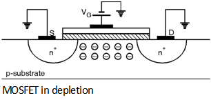
Consider the case that VGS is positive but less than V TH for some terminal biases shown in Figure below. Under these conditions the surface under the gate is depleted because as the holes under the gate are displaced and leave negative immobile ions that contribute to negative charge as shown in Fig. 3.6.3.
In this region of operation the capacitance between the gate and the source/drain is simply overlap capacitance while the capacitance between the gate and substrate is the oxide capacitance in series with depletion capacitance of the formed of depletion region. The MOSFET operated in this region is said to be in weak inversion or the sub threshold region.
When VGS is sufficiently positive and is larger than V TH then a large number of electrons are attracted under the age and the surface is said to be inverted. MOSFET makes a very good capacitor when VGS > VTH + few hundred mV. In integrated circuits the capacitor based on MOSFETs are designed in this region of operation.
The complete C-V characteristics of the MOSFET are shown in Figure below.