Home > mini projects > LOW COST MOSFET BASED MOTOR DRIVER
LOW COST MOSFET BASED MOTOR DRIVER
Abstract -This project proposes a MOSFET-based motor driver circuit, which aims to serve as a cheaper replacement for the currently available ICs in the market. The circuit has the versatility of being paired with a microcontroller, as well as work independently (with speed and direction control).
I. INTRODUCTION
Almost all the fields of education, technology and healthcare are becoming automated day-by-day, thanks to the advent of microcontrollers and ASICs. However, these circuits tend to work at voltages as low as in the order of microvolts, and thus the use of driver circuits were needed. As the name suggests, driver ICs are circuits which run the high power devices based on the small scale signals given to it.
However, most driver ICs in the market are cost demanding, and cannot work independently. We have thus proposed a robust and economical approach for driving a motor, and aim to deal with the above shortcomings. It is assumed that the reader has a basic knowledge of electronics.
II. DESIGN
A. H-Bridges
An H-Bridge is an electronic circuit that enables a voltage to be applied across a load in either direction. These circuits are often used to drive DC motors, stepper motors, power inverters.
A typical H-bridge consists of a set of four switches that an arbitrary load impedance is decoupled from a DC voltage and GND. These switches are alternatively opened and closed in a desired manner to control the direction of current flow.
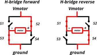
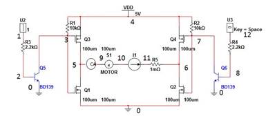
In our circuit, the switching action is implemented through four N-channel, enhancement type power MOSFETs. BJTs and Op-Amps can also be used.
When Q1 and Q4 are on, the left lead of the motor is connected to the power supply and the right lead to the ground. The motor rotates in clockwise direction. When Q2 and Q3 are on, the polarities reverse and the motor spins in an opposite direction.
B. Pulse Witdth Modulation
Pulse Width Modulation (PWM) is a technique which is used to get analog results by digital means. In PWM, the duty cycle of a square wave is varied in proportion to the desired analog voltage. The fast ON and OFF operation is interpreted by the motor as analog voltage, which in turn controls the speed of the motor.
A simple and efficient way of implementing PWM is to use a comparator circuit with inputs as the DC voltage and a unipolar sawtooth wave.
C. Equivalent Circuit of Motor
![]()
The DC motor can be approximated to a series R-L-V combination. For sake of simplicity, we've taken a load resistance of 100k in our circuit.
D. Equations
As the MOSFETs are used as switches, it is mandatory that the be biased in saturation mode when ON and cut-off mode when OFF.
Applying KCL between Vdd, (Q1,Q4) and GND, we get:
Vdd - I(R1) - I(M) - I(R2) - 2*Vds,sat=0 ...(i)
where M is the impedance of the motor. The current required by the motor can be approximated to 1.5A.
Also
Id,sat= Kn(W/2L)(VGS − VT ) ^2 ...(ii)
Solving (i) and (ii), we get the desired values of W,L,Kn.
Vgs can be assumed to be 4.5-5V (logic 1) in ON mode.
Vto can be assumed to be 0-0.5V (logic 0) in OFF mode.
III. OBSERVATIONS
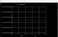
A. Output Voltage and Current (Va=1,Vb=1or Va=0,Vb=0)
Voltage across motor = 900mV
Current in motor =14.7uA
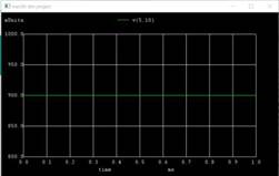
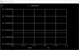
Though the above values are in millisvolts and miliamperes the motor wont rotate in any direction.
B. Output Voltage and Current (Va=0,Vb=1or Va=1,Vb=0)
Voltage across motor= 1.9V
Current in motor = 9A
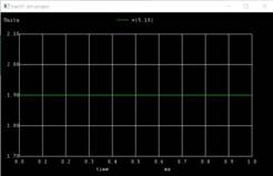
Though the above values are in volts and Amperes, the motor will rotate either in clockwise or anticlockwise direction depending on the input.
C. Observation Table
|
Input A |
Input B |
Output(MotorStatus) |
|
0(Low) |
0(Low) |
Doesn't Run |
|
0(Low) |
1(High) |
Forward Direction |
|
1(High) |
0(Low) |
Reverse Direction |
|
1(High) |
1(High) |
Floating State |
|
IV. |
Result and Conclusions |
|
Though the above values of conditions in (A.) are in millisvolts and miliamperes the motor wont rotate in any direction