Home > mini projects > Bistable Multivibrator using Asymmetrical Mosfet Triggering
Bistable Multivibrator using Asymmetrical Mosfet Triggering
Abstract -An electrically triggerable bistable multivibrator using MOSFET as an asymmetrical trigger source and giving electrical outputs is proposed, designed, and implemented using transistor-transistor logic . The circuit is found to be working satisfactorily .
I. INTRODUCTION
A multivibrator is an electronic circuit used to implement a variety of simple two-state systems such as oscillators, timers and flip-flops. It is characterized by two amplifying devices (transistors, electron tubes or other devices) cross-coupled by resistors or capacitors. There are three types of multivibrator circuits depending on the circuit operation. Bistable multivibrator in which the circuit is stable in either state. It can be flipped from one state to the other by an external trigger pulse. This circuit is also known as a flip flop. It can be used to store a bit of information.
II. DESIGN AND WORKING
The Bistable Multivibrator circuit shown in figure 1 is stable in both states, either with one transistor "OFF" and the other "ON" or with the first transistor "ON" and the second "OFF". Lets suppose that the switch is in the left position, position "A". The base of transistor TR 1 will be grounded and in its cut-off region producing an output at Q. That would mean that transistor TR2 is "ON" as its base is connected to Vcc through the series combination of resistors R1 and R2. As transistor TR2 is "ON" there will be zero output at Q, the opposite or inverse of Q.
A. If the switch is now move to the right, position "B", transistor TR 2 will switch "OFF" and transistor TR1 will
switch "ON" through the combination of resistors R3 and R4 resulting in an output at Q and zero output at Q the reverse of above. Then we can say that one stable state exists when transistor TR1 is "ON" and TR 2 is "OFF", switch position "A", and another stable state exists when transistor TR1 is "OFF" and TR2 is "ON", switch position "B".
» Switching between the two states is achieved by applying a single trigger pulse which in turn will cause the "ON" transistor to turn "OFF" and the "OFF" transistor to turn "ON" on the negative half of the trigger pulse.
» The circuit will switch sequentially by applying a pulse to each base in turn and this is achieved from a single input trigger pulse using mosfets as asymmetric triggering using two different triggering sources.
» Then on the application of a first negative pulse switches the state of each transistor and the application of a second pulse negative pulse resets the transistors back to their original state acting as a divide-by-two counter.
» Equally, we could remove feedback resistors and apply individual negative trigger pulses directly to the transistor bases.
B. the bistable multivibrators output is dependent upon the application of two individual trigger pulses, switch position "A" or position "B".
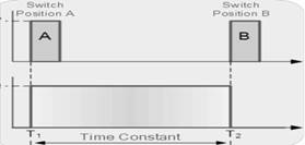
C. So Bistable Multivibrators can produce a very short output pulse or a much longer rectangular shaped output whose leading edge rises in time with the externally applied trigger pulse and whose trailing edge is dependent upon a second trigger pulse
D. Manually switching between the two stable states may produce a bistable multivibrator circuit but is not very practical. One way of toggling between the two states using just one single trigger pulse is shown in the figure.
III.Circuit Diagram
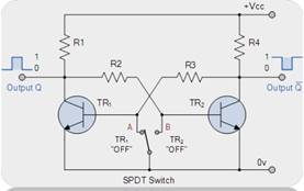
Fig 1
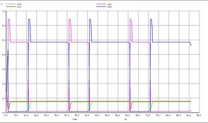
A.The combined output of Q and Qbar along with the trigger pulses
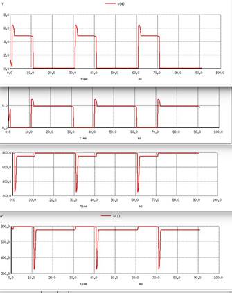
B.The Individual outputs and Trigger pulses
V.CODES
*BISTABLE MULTI VIBRATOR
R1 6 4 3.9K
R4 6 5 3.9K
R2 4 3 47K
R3 2 5 47K
R5 4 2 220K
R8 5 3 220K
*BIASING RESISTOR NETWORK
R6 2 7 10
R7 3 8 10
*TRANSISTORS USED TO MODEL THE CRKT .MODEL BJT NPN
Q1 4 2 0 BJT
Q2 5 3 0 BJT
*OPERATING VOLTAGE
VCC 6 0 DC 7V
*MOSFETS USED FOR ASYMMETRICAL TRIGGERING
.MODEL N NMOS
M1 7 9 0 0 NMOS
M2 8 10 0 0 NMOS
*TRIGGERING PULSES
V1 10 0 PULSE(0 5 10MS 0 0 5US 30MS)
V2 9 0 PULSE(0 5 0 0 0 5US 30MS)
*PERFORMING THE TRANSIENT ANALYSIS
.TRAN 1MS 500MS
*VISUALIZING THE OUTPUTS
.CONTROL
RUN
DISPLAY
SET COLOR0=WHITE
SET COLOR1=BLACK
SET COLOR2=RED
SET COLOR3=BLUE
SET COLOR4=GREEN
SET COLOR5=MAGENTA
PLOT V(2) V(5) V(3) V(4)
.ENDC
.END