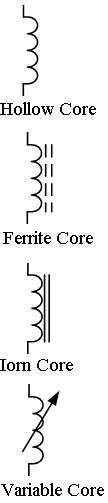
As we know that, when current flows in a conducting wire the magnetic field is developed around the conducting wire. Therefore, there is formation of relationship between the electric current flowing through the wire and the magnetic field induced around the conducting wire. This relationship between the electric current and the magnetic field induced around the conducting wire is given by the Fleming's Right Hand Rule. However, if we keep another such conducting wire in the magnetic field developed around the conducting wire, voltage is induced into the other secondary cable due to the magnetic field and it resists the changes in the electrical current flowing into the first conducting wire. Therefore, inductor is nothing but the coil of wire wind over the core. In this coil, the current, flowing develops the magnetic field around the coil. The developed magnetic field is proportional to the current flowing through the coil. Popularly the inductor is also known as choke The inductor is a passive component having coil of wire which is based on the principle of relation between induced magnetic field and the current flowing through the coil. The inductors are nothing but the wired coils which are wounded over the core. The core can be in the form of cylindrical rod or it can be in the form of ring. The symbols for inductor are shown in bellow figure. The inductors are normally classified according type of inner core used in the inductor. The various types of care are, a) hollow core, b)iron core, c) ferrite core etc.
The electrical current flowing through the inductor develops the magnetic field around the coil and the inductor resists the rate of change of electrical current flowing through the inductor it due to the energy induced in the magnetic field. Hence, inductors resists the changes of the electrical current (i.e. alternating current) and passes the direct current (DC) easily.
Thus inductor, opposes the changes in the electrical current relates the electrical current with the magnetic flux. The constant of proportionality in this relation is known as the Inductance which is denoted by the symbol L and is measured in Henry, (H). The prefix used in the inductor unit are,
1mH that means one mili Henry
1 µH that means one micro Henry
1 nH that means one nano Henry
1 mH= 10-3 H
1 µH = 10-6 H
1 nH= 10-9 H
Inductors are commonly used in electrical circuits. The parameters which decides the value of inductance are,
1) shape of the coil
2) number of turns
3) number of layers of conducting wire
4)spacing between the turns
5) permeability of the core material
6) cross-sectional area of the core.
The inductor parameters are denoted as, central core area, ( A ) having number of turns of wire per unit length, ( l ). Therefore, if a coil has N turns and an amount of magnetic flux, Φ then the coil has a flux linkage of NΦ and the current, ( i ) flows through the coil generates magnetic flux in the opposite direction to the flow of current.
Hence, according to Faraday's Law, change in magnetic flux linkage produces a self-induced voltage in the single coil of which is given by,
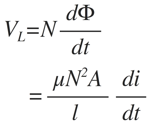
Where:
N is the number of turns, A is the cross-sectional Area in m2, Φ is the amount of flux in Webers, μ is the permeability of the core material, l is the length of the coil in meters and di/dt is the currents rate of change in amps/second
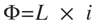
Hence, time varying magnetic field induces voltage which is proportional to the rate of change of current and inducing electromotive force (emf). The above equation which relates self-induced voltage, current and inductance is developed by substituting the μN2A / l with L which is known as the Inductance of the conducting wire. The relation between magnetic flux and the electrical current is given by,
From above equation, the back emf induced in the coil is given as,
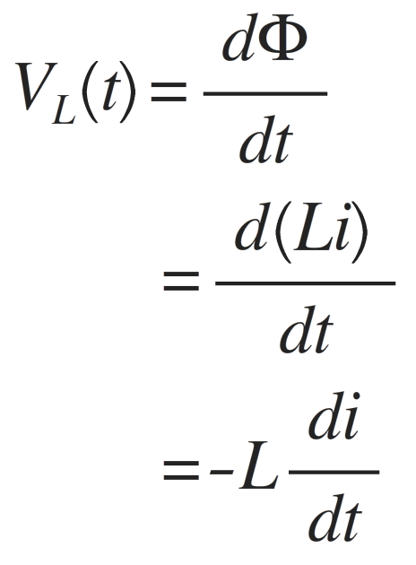
where: L is the self-inductance and
di/dt is the rate of current change.
From above equation it can be seen that,
self-induced emf = inductance x rate of current change
Hence in the circuit one Henry inductance has emf of one volt induced in the circuit when the current in the circuit changes one ampere per second.
Further, when DC current flows in the inductor zero emf induces cross it and hence the inductor works like short circuit wire.
Power in Inductor
As inductor in circuit opposes the current flowing through it, the power forcing the current, ( i ) against this self-induced emf, ( VL ) is given by,
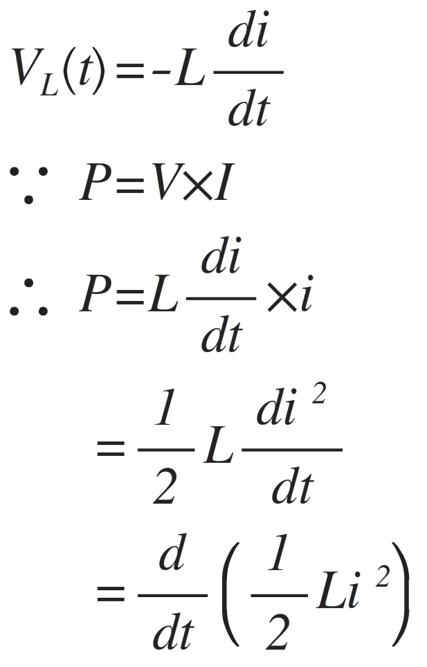
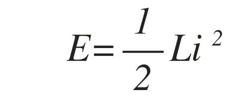
Energy in Inductor
As we know that, when power flows in the inductor, energy is stored in its magnetic field and if current increases and di/dt is greater than zero, the power in the circuit is greater than zero. Hence, energy is stored in the inductor. Further, if the current in the inductor is decreasing and di/dt is less than zero then the power is less than zero. Hence, negative power shows that, the inductor is returning energy back into the circuit. Therefore, the energy stored in the inductor is given by,