Home > mini projects > Four bit Arithmetic Logical Unit
Abstract - The project is an attempt to portray the skills of NGSpice attainted over the semester with simulation of a complex circuit. The circuit is that of an arithmetic logical unit which can perform adding and subtracting, along with all the 4 logic gate operations.
Keywords-ALU; gates; MUX
I. INTRODUCTION
Basic circuits in electronics involve the use of gates. The digital logics are further used to develop more complex device. Arithmetic operations are an integral part of any system. A basic 4-bit ALU here performs addition, subtraction and the operations on ANDing, ORing, inverting and XORing.
A. Equations
For the adder and subtractor, the basic equations used are :
SUM = A XOR B = A ⊕ B CARRY = A AND B = A.B For the logical operators, the equations are : AND - Q = A.B
OR - Q = A+B
NOT - Q = A`
XOR - Q = A⊕B
B. Figures and Tables i) Logical Operators
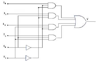
Fig 1.
The above figure is of a 4x1 Multiplexer. The inputs to the mux I0, I1, I2, I3 are connected to the outputs of the gate. The select lines s0 and s1 are used to select between the 4 inputs, according to the operation which the user wants to perform.
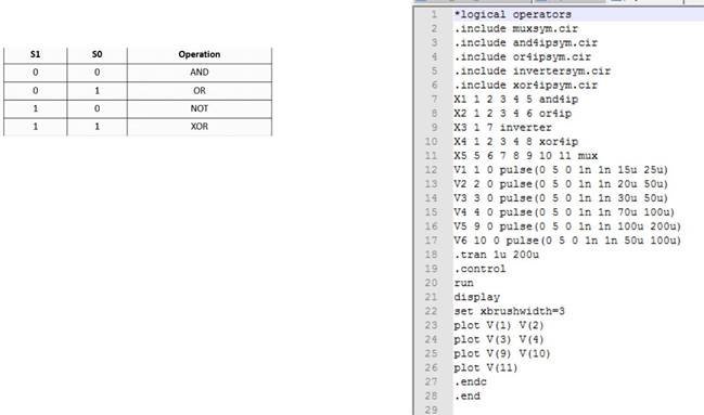
The select lines work according to the following truth table -
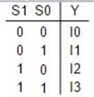
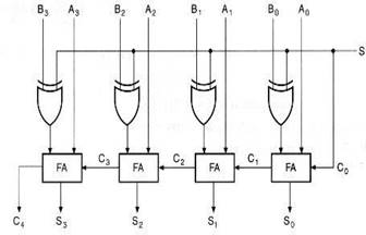
Fig 3.
A0A1A2A3 and B0B1B2B3 are given as the 4-bit inputs for addition and subtraction.
EXPLAINATION
For the logical operators, the symbols for the 4 gates are created, namely AND, OR, NOT and XOR. Outputs from all the gates are obtained. A symbol for multiplexer 4x1 is created in NGSpice. The inputs to this mux are the outputs of the four gates. These outputs are selected by the select inputs to the mux, s0 and s1.
For the adder and subtractor, a control signal controls if addition takes place or subtraction for the 4-bit inputs. The symbols for full adder are used for the same.
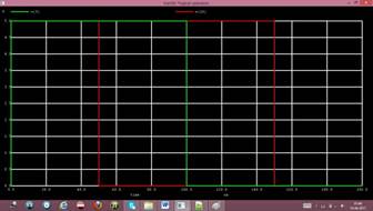
CODE AND PLOTS
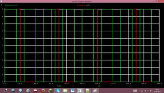
V(18)-S2 V(20)-S3
V(1)-Input A V(2)-Input B
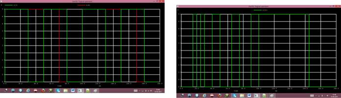
V(3)-Input C V(4)-Input D
V(11)-Output