The following circuit diagram shows op-amp as a buffer amplifier,
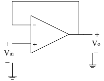
The input is applied at the non-inverting terminal of op-amp. The output terminal and the inverting terminal are at the same potential.
From the figure, due to virtual ground concept, the voltage at inverting terminal appears to be same as input voltage Vin. As mentioned above inverting terminal and the output terminal are at the same potential, we can have the output as,
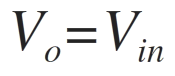
Thus the output voltage Vo is equal to input voltage Vin. If Vin increases, Vo also increases. If Vin decreases, Vo also decreases. Thus output follows the input hence the circuit is also called as voltage follower.
The gain of the circuit is 1; hence it is also called as unity gain amplifier. It is also called as buffer amplifier or source follower.
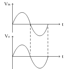
The input and output waveforms are shown below.
Advantages:
1) High input impedance.
2) Low output impedance.
3) High bandwidth.
4) The output follows input without phase shift.