Home > VHDL > Introduction > Structural modeling
Structural Modelling :
In structural modeling the components of the system are listed and the interconnections between them are specified. In this modeling the designs are described in the form of block diagrams. Components represented by blocks are interconnected by lines representing signals.
VHDL Structural modeling code should have 1) ability to define the list of components, 2) definition of a set of signals, 3) ability to uniquely label the component and 3) ability to specify signals to ports.
COMPONENT :
COMPONENT linked with, LIBRARY declarations, ENTITY, ARCHITECTURE. However, by declaring COMPONENT, it can be used within another system. The syntaxes are as follows,
COMPONENT declaration :
  COMPONENT component_name IS
  PORT (
  port_name : signal_mode signal_type;
  port_name : signal_mode signal_type;
  ...);
  END COMPONENT;
COMPONENT instantiation :
label: component_name PORT MAP (port_list);
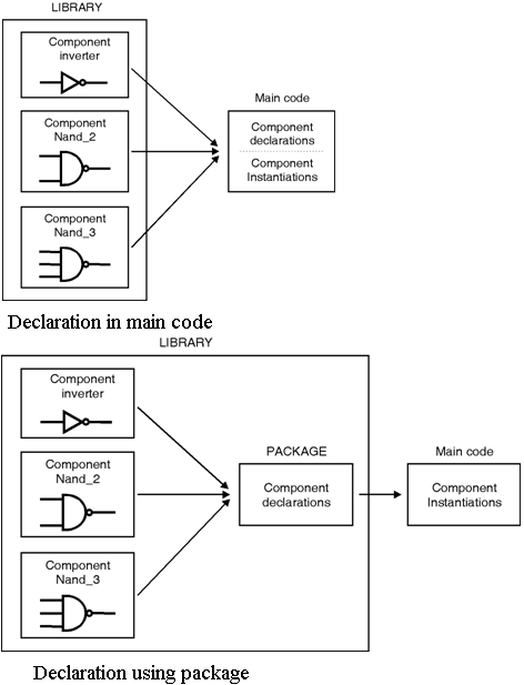
From the syntax it can be seen that, the declaration is similar to that of an ENTITY. To instantiate the component a label is mandatory, followed by the name of component and PORT MAP declaration. There are two ways to declare a COMPONENT. 1) designed and placed in the destination LIBRARY 2) declared in the main code or declared using a PACKAGE. Figure below show the component declarations.
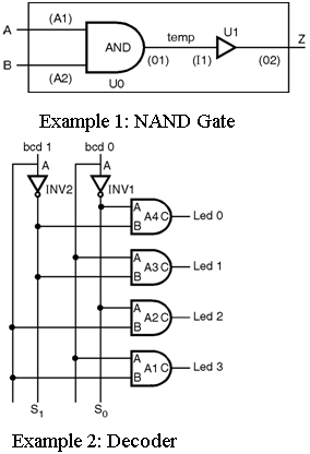
Example 1 : Structural architecture for NAND2
  architecture STRUCTURAL of NAND2 is
  signal temp: BIT;                                   -- (internal) signal declaration
  component AND2                      -- AND2 component declaration
  port	(A1, A2: in BIT;
  O1: out BIT);
  end component;
  component INVERT                   -- INVERT component declaration
  port	(I1: in BIT;
  O1: out BIT);
  end component;
  begin
  U0: AND_2 port map (I1 => A, I2 => B, O1 => I);
  U1: INVERT port map (I1 => I, O1 => Z);
  end STRUCTURAL;
Example 2 : Structure architecture of Decoder The components Inverter and AND_Gate are instantiated under the names Inv1, Inv2, A1, A2, A3 and A4. The connections among the components are realized by the use of signals S(0), S(1) declared in the architecture's declarative part.
  architecture Structural of Decoder is
  signal S: Bit_Vector(0 to 1);
  component AND_Gate
  port(A,B:in Bit; C:out Bit);
  end component;
  component Inverter
  port(A:in Bit; B:out Bit);
  end component;
  begin
  Inv1:Inverter port map(A=>bcd(0), B=>S(0));
  Inv2:Inverter port map(A=>bcd(1), B=>S(1));
  A1:AND_Gate port map(A=>bcd(0), B=>bcd(1), C=>led(3));
  A2:AND_Gate port map(A=>bcd(0), B=>S(1), C=>led(2));
  A3:AND_Gate port map(A=>S(0), B=>bcd(1), C=>led(1));
  A4:AND_Gate port map(A=>S(0), B=>S(1), C=>led(0));
  end Structure;