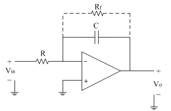
The limitations of an ideal integrator can be minimized in the practical circuit by adding resistor Rf in parallel with capacitor C this Rf avoids op-amp going into open loop configuration at low frequencies.
The practical integrator circuit is shown below.
Frequency response of practical integrator:
The voltage gain 'A' is given by the equation as follows,

Let fa=1/(2πRf C) =≫Break frequency or Corner frequency
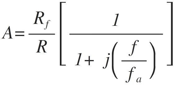
Where f=≫Operating frequency
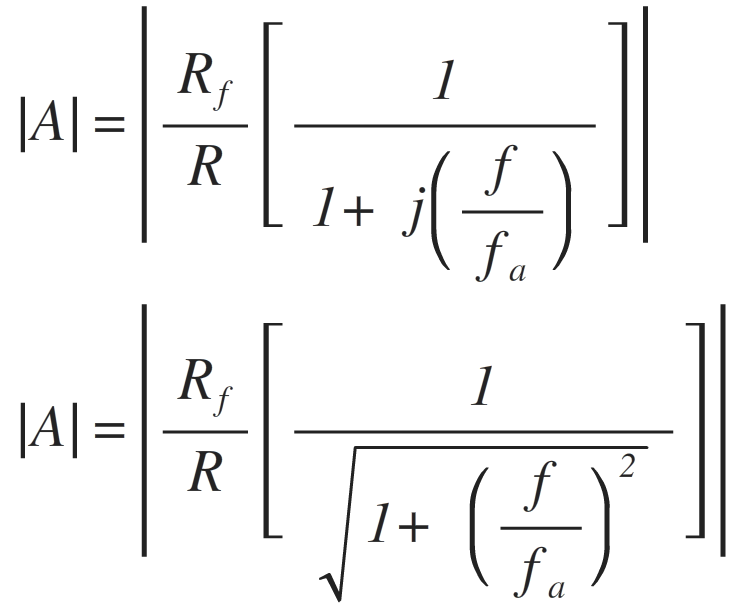
The magnitude of gain A is,
Consider the following cases:
1. When f=0 ,the gain |A|=|Rf/R|—–dc gain
2. When 0<f<fa ,the gain |A|≅|Rf/R|
3. When f>fa ,the gain |A|≪|Rf/R|
4. When f= fa , the gain |A|=|Rf/R (1/√2) | Hence, |A|=|0.707 (Rf/R) |
The gain in dB is given as
20log |A|=20log |0.707 (Rf/R) |
|A| in dB=20log (0.707)+20log (R_f/R)
|A| in dB=20log (Rf/R) – 3dB
|A| in dB=DC gain (i.e.maximum gain) – 3dB
Thus the frequency fa is the frequency at which gain is reduced by 3 dB from its maximum value. Hence frequency fa is also called as 3dB frequency.
From ideal integrator response, we have defined frequency fb which is 0dB frequency (or unity gain frequency).
The detailed frequency response of practical integrator is shown in figure below.
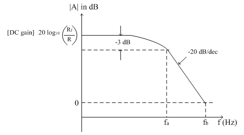
Between the frequency ranges fa to fb the response is highly linear and dropping at the rate of -20dB/decade. Thus the frequency range fa to fb referred as true integration range where actual integration of the input signal is possible.
Thus the true integration is possible over the range fa<f<fb
The practical integrator is also called as lossy integrator as it integrates only frequencies greater than fa (i.e. higher frequencies) effectively.
Thus we can have following observations from frequency response of practical integrator:
1. Bandwidth of practical integrator is fa which is higher than BW of an ideal integrator.
2. DC gain (at f=0) is |Rf/R| which is typically ≥10.
3. For better integration fb≥10fa.
4. For proper integration Time period T of input signal ≥Rf C