In this amplifier the input signal and output signal are in phase i.e. the phase shift is 0̊. The following circuit diagram shows the non-inverting amplifier using op-amp.
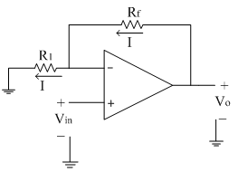
The input signal is applied at the non-inverting terminal of op-amp. Due to the virtual ground concept, the inverting terminal of op-amp is also appears to be at the same potential Vin.
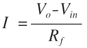
Assume current ‘I’ is flowing through the feedback resistance Rf.
The current ‘I’ can be calculated as,
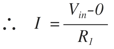
Since input current to the op-amp is zero, same current ‘I’ flows through the resistance R1.
Comparing the above two equations,
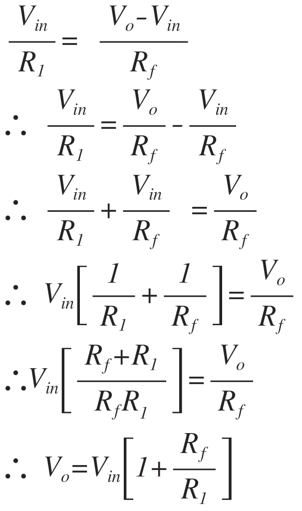
The positive sign indicates that both input and output are in phase. The input and output waveforms are shown below.
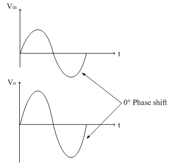
Important points:
The phase shift between input and output is 0̊ i.e. input and output are in phase.
The voltage gain is always greater than 1.
The voltage gain is dependent on two resistances R1 and Rf. By changing the values of the two resistances required gain can be adjusted.