Home > mini projects > 4 Bit Binary Counter
Abstract - In our day to day life we come across situation in which we require a system which gives us data in specific fashion in order to achieve such pattern we make use of electronics circuits. In this project we synthesized a circuit that saves a lot of board space and time required to build circuits when application demands.
I. I NTRODUCTION
Today, the semiconductor industry is giving serious consideration to the adoption of asynchronous circuit technology. Up until now, asynchronous circuits have been applied commercially only as small subcircuits, often as peripherals to controllers. Examples include counters, timers, wakeup circuits, arbiters, interrupt controllers, first-in first-out (FIFO), bus controllers, and interfaces (e.g., RS-232, SCSI, UART). The need for such asynchronous circuits stems largely
For example, a binary mod 16 counter has 16 countable states. They are from 0000 to 1111. So the mod 16 counter counts from 0 to 16.
Similarly binary mod 4 counter has 4 count states, from 000 to 011. So the mod 4 counter counts from 0 to 4. This means, in general a mod N counter can contain n number of flip flops, where 2n = N..
II. N EED OF C OUNTERS
Counting means incrementing or decrementing the values of an operator, with respect to its previous state value. So to perform the mathematical operation we use no devices other than counters. We cannot perform this action (counting) with any other logic devices rather than counters.ns
A. Types of counters :
- SYNCHRONOUS COUNTERS:
The counters which use clock signal to change their transition are called "Synchronous counters". This means the asynchronous counters do not depends on their clock input to change state values. All flip flops in the asynchronous counters are triggered by output of previous stage.
- FEATURES:
Their construction is very simple in design. All the flip flops are interconnected.
The state output of the previous flip flop determines the state change of the present flip flop. As all the flip flops will work asynchronously.We require number of logic gates to implement the asynchronous counters. Their operation is comparatively slower then the synchronous counter part.
- ASYNCHRONOUS COUNTERS
Definition: The counters in which the change in transition doesn't depend upon the clock signal input is known as "Asynchronous counters". In these counters, the first flip flop is connected to the external clock signal, and the rest are clocked by the state outputs (Q & Q') of the previous flip flop.
- FEATURES:
Another name for Asynchronous counters is "Ripple counters".These are very simple in design. As its design is simple, they use less number of logic gates to construct an asynchronous counter. Operation of asynchronous counters is slow compared to synchronous counters.
III. CIRCUIT:
The following the circuit used for counter implementation
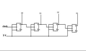
IV. C OMPONENTS :
1. T-flipflops (x4): T-flipflops are cascaded to generate a 4 bit-counter. This was formed using sub circuit of master slave JK flipflop.
2. NAND Gate (x8):It's sub circuit was used to make nand circuit
3. Inverter (x4): Inverter circuit is used as one of the clock inputs CP1' and buffer is used as the other clock input.
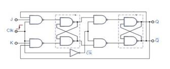
When Master Reset goes high, it resets the counter to zero, independent of the clock inputs (CP0 and CP1).
B. Clock Inputs: The counter is advanced by either a low-to-high transition at one of the inputs while the other input is low or a high-to-low transition at the second input while first input is high.
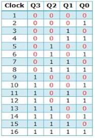
Truth table of counter
-
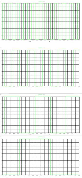
V. W AVEFORMS :
Input Clock: