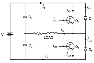
A single phase Half Bridge DC-AC inverter is shown in Figure below,
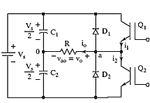
The analysis of the DC-AC inverters is done taking into accounts the following assumptions and conventions.
1) The current entering node a is considered to be positive.
2) The switches S1 and S2 are unidirectional, i.e. they conduct current in one direction.
3) The current through S1 is denoted as i1 and the current through S2 is i2.
The switching sequence is so design is shown in Figure below. Here, switch S1 is on for the time duration 0 ≤ t ≤ T1 and the switch S2 is on for the time duration T1 ≤ t ≤ T2. When switch S1 is turned on, the instantaneous voltage across the load is ν o = Vin/ 2
When the switch S2 is only turned on, the voltage across the load is
ν o = ̶ Vin/ 2.

The r.m.s value of output voltage ν o is given by,
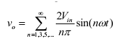
The instantaneous output voltage ν o is rectangular in shape. The instantaneous value of ν o can be expressed in Fourier series as,
Due to the quarter wave symmetry along the time axis , the values of a0 and an are zero. The value of bn is given by,
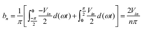
Substituting the value of bn from above equation 5, we get
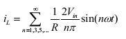
The current through the resistor ( iL ) is given by,
Half Bridge DC-AC Inverter with L Load and R-L Load
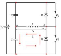
The DC-AC converter with inductive load is shown in Figure below. For an inductive load, the load current cannot change immediately with the output voltage.
The working of the DC-AC inverter with inductive load is as follow is:
Case 1: In the time interval 0<=t<= T1 the switch S1 is on and the current flows through the inductor from points a to b. When the switch S1 is turned off (case 1) at t-T1, the load current would continue to flow through the capacitor C2 and diode D2 until the current falls to zero, as shown in Figure below.
Case 2: Similarly, when S2 is turned off at t = T1 , the load current flows through the diode D1 and capacitor C1until the current falls to zero, as shown in Figure below.
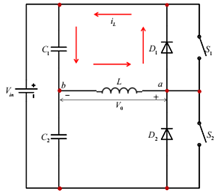
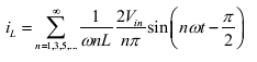
When the diodes D1 and D2 conduct, energy is feedback to the dc source and these diodes are known as feedback diodes. These diodes are also known as freewheeling diodes. The current for purely inductive load is given by,
Similarly, for the R – L load. The instantaneous load current is obtained as,
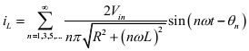
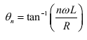
Where,