Statement of Thevenin’s theorem :
Any network containing active and/or passive element and one or more dependent and/or independent voltage/or current sources can be replaced by an equivalent network containing a voltage source (Thevenin’s equivalent voltage VTH or Voc) and a series impedance (called Thevenin equivalent impedance ZTH). VTH or VOC is called as the Thevenin's equivalent voltage. It is the open circuit voltage measured at the two terminals of interest with the load impedance ZL removed. ZTH is the Thevenin's equivalent impedance. It is the impedance measured between the load terminals with ZL removed and with all the independent voltage/current sources replaced by their internal impedances.
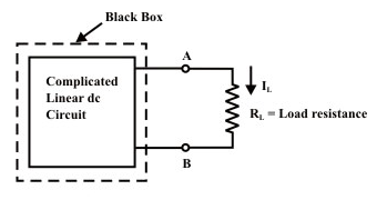
A simple circuit as shown in above figure is considered to illustrate the concept of equivalent circuit and it is always possible to view even a very complicated circuit in terms of much simpler equivalent source and load circuits. Subsequently the reduction of computational complexity that involves in solving the current through a branch for different values of load resistance (R) is also discussed. In many applications, a network may contain a variable component or element while other elements in the circuit are kept constant. If the solution for current (I) or voltage (V) or power (P) in any component of network is desired, in such cases the whole circuit need to be analyzed each time with the change in component value. In order to avoid such repeated computation, it is desirable to introduce a method that will not have to be repeated for each value of variable component. Such tedious computation burden can be avoided provided the fixed part of such networks could be converted into a very simple equivalent circuit that represents either in the form of practical voltage source known as Thevenin's voltage source or in the form of practical current source known as Norton's current source. In true sense, this conversion will considerably simplify the analysis while the load resistance changes.
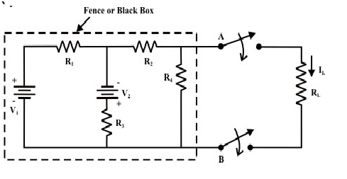
Let us consider the circuit shown in figure. Our problem is to find a current through RL using different techniques; the following observations are made.
Find
• Mesh current method needs 3 equations to be solved
• Node voltage method requires 2 equations to be solved
• Superposition method requires a complete solution through load resistance (RL) by considering each independent source at a time and replacing other sources by their internal source resistances.
Suppose, if the value of RL is changed then the three (mesh current method) or two equations (node voltage method) need to be solved again to find the new current in RL. Similarly, in case of superposition theorem each time the load resistance RL is changed, the entire circuit has to be analyzed all over again. Much of the tedious mathematical work can be avoided if the fixed part of circuit or in other words, the circuit contained inside the imaginary fence or black box with two terminals & AB, is replaced by the simple equivalent voltage source or current source.

Procedure for applying Thevenin's theorem
To find a current IL through the load resistance RL as shown in figure using Thevenin's theorem, the following steps are followed,
Step-1: Disconnect the load resistance (LR) from the circuit, as indicated in figure
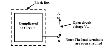
Step-2: Calculate the open-circuit voltage VTH at the load terminals (A&B) after disconnecting the load resistance (RL). In general, one can apply any of the techniques (mesh-current, node-voltage and superposition method) to compute (experimentally just measure the voltage across the load terminals using a voltmeter).
Step-3: Redraw the circuit with each practical source replaced by its internal resistance as shown in figure. (note, voltage sources should be short-circuited (just remove them and replace with plain wire) and current sources should be open-circuited (just removed).

Step-4: Look backward into the resulting circuit from the load terminals (A&B) , as suggested by the eye in figure. Calculate the resistance that would exist between the load terminals ( or equivalently one can think as if a voltage source is applied across the load terminals and then trace the current distribution through the circuit in order to calculate the resistance across the load terminals. The resistance RTh is described in the statement of Thevenin's theorem. Once again, calculating this resistance may be a difficult task but one can try to use the standard circuit reduction technique or transformation techniques.
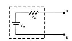
Step-5: Place in series with to form the Thevenin's equivalent circuit (replacing the imaginary fencing portion or fixed part of the circuit with an equivalent practical voltage source) as shown in above figure.
Step-6: Reconnect the original load to the Thevenin voltage circuit as shown in figure; the load's voltage, current and power may be calculated by a simple arithmetic operation only.
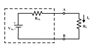
Load current
Voltage across the load
Power absorbed by the load
Steps to be followed to apply the Thevenin’s theorem :
Step 1 :Remove the branch, the current through which is to be obtained.
Step 2 :Calculate the open circuit voltage Voc or RTH .
Step 3 :Obtain RTH between the open circuited points.
Step 4 :Draw the Thevenin's equivalent circuit and connect the removed branch as load to find the branch current.


