Home > finite state machines > Hazards > Static Hazards
Static Hazards :
- A static hazard in a logic network is a transient change of an output value which is supposed to remain fixed during the transition between two input states differing in the value of only one variable.
- When the output is supposed to remain at “0â€, but it is likely to go high (to logic 1) momentarily during the transition of input states, then the hazard is called as a static 0 hazard.
- A static 0 hazard is shown in Figure below.
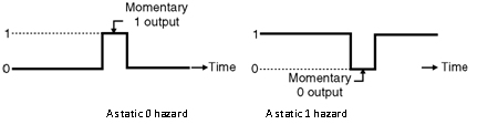
(a) A static 0 hazard (b) A static 1 hazard - On the other hand if a momentary “0†is likely to occur in the output when it is expected to remain “1â€, then the hazard is called as a static 1 hazard.
- A static 1 hazard is shown in Figure. Illustration of Static 0 Hazard :
- Figure below shows a combinational circuit with hazards and the relevant waveforms.
- Initially A = 0 and B = 1. Hence output G1 = 0 and G2 = 1.
- At t = t1, A changes its state to become 1. So now A = B = 1. The output of gate 1 i.e. G1 becomes high after a time delay equal to the propagation delay of AND gate 1.
- The output of gate 2 i.e. G2 goes low after a time delay which is equal to the sum of propagation delays of the inverter and the AND gate-2.
- Hence output Y goes high for a short duration as shown in Fig. 2.12.2(b).
This short duration HIGH pulse is unwanted and called as a static 0 hazard.
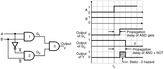
Illustration of Static 1 Hazard : Consider the network of Figure below. Let the input status initially be ABC = 1 1 1.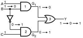
- So the initial gate outputs are G1 = 1 and G2 = 0
- Where as the initial output Y = 1.
- Now let the input state be changed to ABC = 101 from 111. i.e. the value of only B input is changed.
- Due to this change in input, the gate outputs change as follows : G1 = 1 ï‚® 0, G2 = 0 ï‚® 1
- The final output Y is expected to remain 1 even for the changed input state. But practically it does not happen so, if the NOT gate has an appreciable propagation delay.
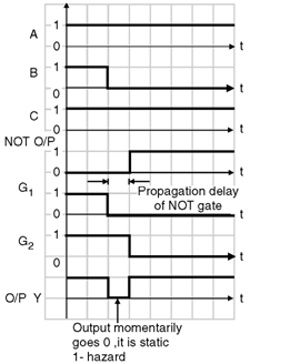
- The effect of long propagation delay of the NOT gate is illustrated in Figure.
- Thus output Y goes to 0 momentarily as shown in Figure below.
- This is called as static 1 hazard.
- We have illustrated the static hazards by assuming the propagation delay of a NOT gate to appreciably longer than the other gates.
- But in practice, each gate will have a finite propagation delay resulting in delays being distributed throughout the network.
- Depending on the value of delays, momentary output signals can occur. Thus even the two level logic networks can have hazards.
- The term hazards specifies the unwanted switching transients or false outputs or glitches which appear at the output of a circuit. These transient false outputs are due to finite propagation delay times of the components along different paths within the network.
- Difference in the propagation delays corresponding to different signal paths result in hazards.
- A hazard can be defined as the actual or potential malfunction of a logic network during the transition between two input states when a single variable changes.
- Malfunctioning means any deviation from the intended response.
- In the combinational circuits, the hazards will result in a false output value. But if such combinational circuits are used as a building block of an asynchronous sequential circuit then it will result in a transition to incorrect stable state.