The following circuit diagram shows the basic 2 bit R-2R ladder DAC circuit using op-amp. Here only two values of resistors are required i.e. R and 2R. The number of digits per binary word is assumed to be two (i.e. n = 2). The switch positions decides the binary word ( i.e. B1 B0 )
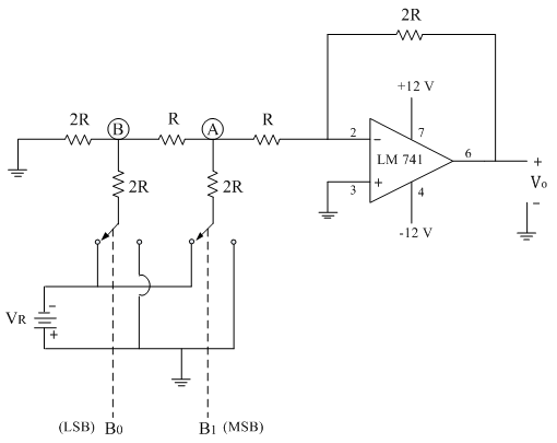
The typical value of feedback resistor is Rf = 2R. The resistance R is normally selected any value between 2.5 kΩ to 10 kΩ.
The generalized analog output voltage equation can be given as

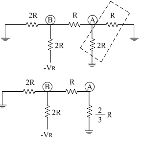
The operation of the above ladder type DAC is explained with the binary word (B1B0= 01)
The above circuit can be drawn as,
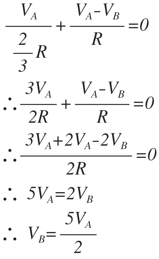
Applying the nodal analysis concept at point (A), we gets following equations
Applying the nodal analysis concept at point (B), we gets following equations
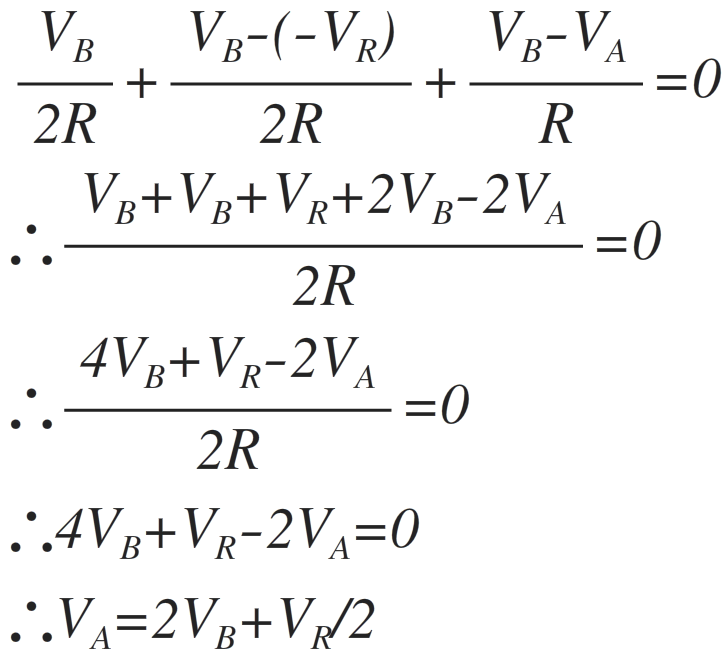
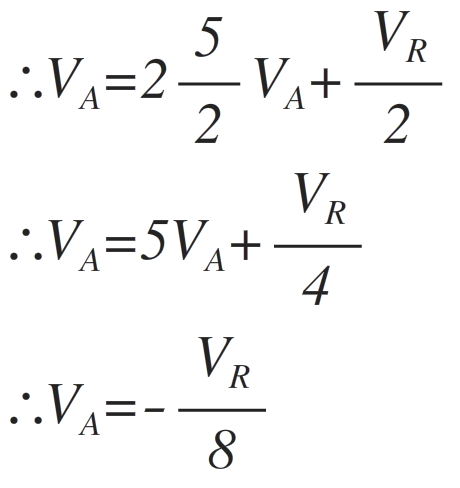
Substituting the equation of VB in the above equation, we get
The voltage at point A i.e. VA is applied as input to the op-amp which is in inverting amplifier mode as shown in figure below.
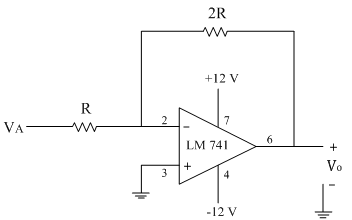
The output voltage of the complete setup
∴Vo=-(2R/R) VA
∴Vo=-(2R/R)(-VR/8)
∴Vo=VR/4
Similarly for other three combinations of digital input the analog output voltage Vo is calculated as follows
